1. Isolated power system design
An isolated power system completes the DC/DC conversion, using a full-bridge topology with an output voltage of 12V. Among them, the original side driver of the whole bridge uses UCC27201, a total of two.
1.1 Isolated Power System Brief
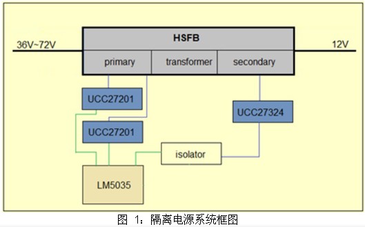
The isolated power system performs a wide range of input voltage (36V~72V) to 12V conversion with an output power of 350W. The system uses a hard-switched full-bridge topology (HSFB) with synchronous rectification. Figure 1 shows a block diagram of the system, including the master chip LM5035, the driver UCC27201 placed on the primary side, the driver UCC27324 on the secondary side, and the isolator.
1.2 Application of UCC27201
The UCC27201 is a MOSFET driver with floating function. It has two channels of high-side output and low-side output. It can be applied to topologies such as BUCK, half-bridge and full-bridge. The chip pins are described as follows:
â— VDD (Pin1): power supply pin, the range is 8V~17V, and the typical value is 12V.
â— VSS (Pin7): chip ground pin;
â— HI, LI (Pin5, Pin6): high-end drive input and low-end drive input;
â— HO, LO (Pin3, Pin8): high-end drive output and low-end drive output;
â— HB, HS (pin2, pin4): floating power supply and floating pin for high-end drive power supply;
As shown in Figure 2, in this power system, the two outputs of one UCC27201 drive the two MOSFETs on the same side of the full bridge, and the main connection network is labeled as blue font. The other output of the other UCC27201 is the other side of the bridge that drives the full bridge.
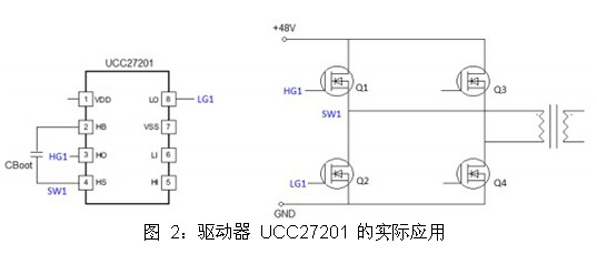
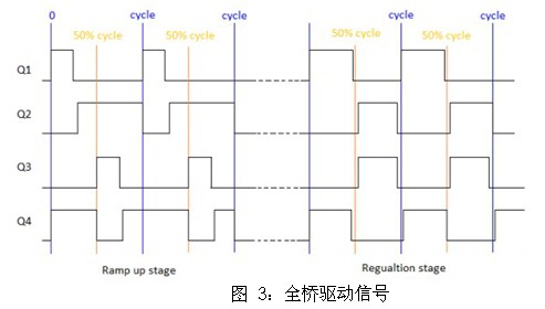
The actual drive signal using the above application circuit is shown in Figure 3, including the soft start and normal operation.
During the soft-start phase, the duty cycle of the drive signal for the MOSFET labeled Q1 is much less than 50%, while the duty cycle for the drive signal for Q2 is more than 50%, which is complementary to the duty cycle of the drive signal for Q1. The relationship between the Q3 and Q4 drive signals is the same as above.
In the normal operation phase, the duty ratios of the driving signals of Q1~Q4 are all close to 50%. The relationship between them is shown in Figure 3, where Q1 and Q2 remain complementary and Q3 and Q4 remain complementary.
modern ceiling lamp is very suitable for Living Room,Dining Room,Study room,Bedroom,Restaurant,Lobby, Bar,Coffe shop and so on.
modern style ceiling light is a fashionable modern light,it is very suitable for living room or bedroom or hotel or engineering or bed room.
modern ceiling light,modern ceiling lamp,modern style ceiling light
Monike lighting , https://www.monikelight.com