Design of Digital Repeater Based on GC5016
For the third-generation mobile communication system, various countries have proposed a variety of different standards. It is very difficult to unify these standards. The development strategy of IMT-2000 has changed the concept of "unification" in the past and turned to the existing second Based on the generation system network to formulate a more realistic transition plan, put forward the concept of "IMT-2000 family". It gave up the consistency of air interface, network technology and other efforts, and is committed to the development of network interface standards and interworking solutions. And there are two standard systems of GSM and CDMA in the second generation mobile communication system. Therefore, there are multiple frequency, multi-mode, multi-system, and multi-standard problems in the future repeaters of mobile communications, which have put forward practical requirements for the application of software radio technology in repeaters. In order to improve the cost performance of 3G repeaters, it is a better solution to use digital technology to unify the hardware platform of 3G repeaters.
Introduction to GC5016
GC5016 is a broadband four-channel programmable digital up-conversion / down-conversion converter launched by TI. It provides 160MSPS clock, outstanding 3G performance, flexible broadband digital filtering, multiple input and output interface options, and ultra-low power consumption. At the same time, it can also be used as an ordinary digital filter.
In the up-conversion mode, the channel receives real data or complex data, extracts with programmable values ​​1 to 4096, and modulates it to the selected center frequency. The modulated signal can be the sum of the signals of the four channels, or it can be the sum of the modulated signals of other GC5016 chips. Channels can be used in pairs to increase the output sampling rate or increase the bandwidth of the input signal, or to achieve both goals simultaneously. Each channel contains a user programmable input filter (PFIR), which can be used as a shaping filter for transmitted data or a Nyquist filter for generating QPSK, GMSK, or QAM signals.
In the down-conversion conversion mode, the channel receives real data or complex data, and demodulates to the selected carrier frequency, and then extracts with a programmable value of 1 to 4096, and then performs automatic gain control amplification, and generates a 20-bit Output. In the down-conversion conversion mode, after the channel output signal is formatted, it is added to the four output ports in the form of real or complex numbers to complete the down conversion of the digital signal.
In the down-conversion channel mode, the input clock rate of 4 channels of GC5016 can reach 160MS / s, while 2 channels can reach 320MS / s, and 4 groups of wideband down-conversion channels can support UMTS standard, with a 115dB distortion-free dynamic range ( SFDR) has 16 FIR filters with up to 255 orders, 64 parallel input / output bits, and flexible I / O options.
The performance of the up-conversion channel mode and the down-conversion mode are basically the same. The output can be independent, it can be the sum of one or two outputs, or it can be the fusion of any several GC5016 chip output signals.
Introduction to Analog Repeater
At present, the block diagram of a mature repeater that is processed by analog is shown in Figure 1 (taking a broadband repeater as an example), where the downlink is a repeater that receives the signal from the base station through the antenna and passes through a low-noise amplifier ( LNA), radio frequency filter (RF Filter), mixer (down conversion), intermediate frequency sound table filter (IF Filter), mixer (up conversion), radio frequency filter (RF Filter), power amplifier drive module ( Amp) and power amplifier (PA), and then transmit through the antenna; the uplink is the repeater receives the mobile station (usually a mobile phone or car phone) through the antenna, after similar processing as the downlink, it is transmitted to the antenna Base station.
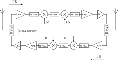
Figure 1 Block diagram of analog repeater system
In order to meet different systems and standards, current repeaters must replace the IF Filter module. The repeaters with different system standards have different hardware configurations, greatly increasing the cost of R & D, production and maintenance.
Digital repeater design
â— Digital IF block diagram
With the development of A / D, D / A and digital signal processing technologies, software radio technology can now be used in the intermediate frequency filtering unit of repeaters, as shown in Figure 2. Using a digital intermediate frequency unit module shown in Figure 2 to directly replace the analog intermediate frequency filter unit (IF Filter) module in Figure 1 (including both upstream and downstream modules) can basically meet the requirements of all current system standards for repeater hardware . In this way, the hardware platform of the repeater is basically unified, as long as different digital filter configuration codes are used, repeater functions of different standards can be realized. The digital filtering function can be realized by high-speed DSP chip, FPGA or dedicated ASIC

Figure 2 Digital intermediate frequency unit box
â— Chip selection
Based on uplink / downlink symmetry and cost considerations, the A / D and D / A chips here have selected dual-channel integrated chips. Among them, A / D chooses ADS5553; D / A chooses DAC5687; Digital filtering adopts special ASIC chip GC5016 to realize.
The resolution of the ADS5553 is 14 bits, the sampling rate is 65 MS / s, the signal-to-noise ratio (SNR) at 70 MHz fIN is 74 dBFs, and the SFDR is 84 dBc.
DAC568 can not only provide signal-to-noise ratio (SNR) greater than 75dB, and third-order intermodulation (IMD3) greater than 81dBc, but also allow multi-carrier systems to work at higher output power. In addition, the power consumption of the DAC5687 at a rate of 500MS / s is only 700mW, which improves system reliability and achieves a higher channel density.
System Configuration
Based on the above digital intermediate frequency hardware platform, it can be applied to repeaters of different standards through different configurations. Now, WCDMA repeaters are used as examples for detailed description.
Set the input analog intermediate frequency (IF) to 140MHz and the sampling frequency of the ADC5553 to 61.44MHz. Using passband undersampling technology, the output rate of ADC5553 is 61.44MS / s. GC5016 receives the signal output from ADC5553, down-converts and filters the signal rate to 7.68MS / s, and then performs up-conversion processing to output an intermediate frequency digital signal with a rate of 61.44MS / s. DAC5687 receives the signal output by GC5016, and outputs an IF analog signal of 140MHz through interpolation and filtering.
ADC5553 does not need software configuration, just give it a stable 61.44MHz clock. The filtering function of the system is mainly realized in GC5016. The requirements of WCDMA for filtering are shown in Figure 3. DAC5687 needs to complete the functions of interpolation / filtering and up-conversion, which can be programmed through the serial interface.
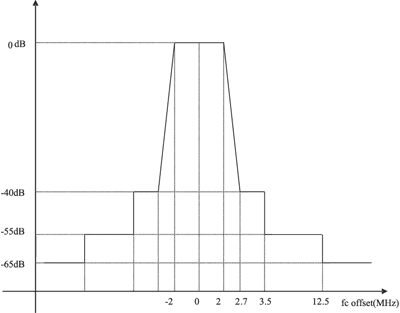
Figure 3 Single-channel filter amplitude-frequency characteristics
The GC5016 can use the CMD5016 configuration software program to generate a series of output files as required. This contains configuration files, analysis files, debug files, and list files. The configuration file defines the settings of all registers in one format to suit the estimation mode of GC101. The analysis file provides gain feedback information from the user to the chip, and provides other useful information for the user to read. The debug file is for the debugger of the software program, and this file may be kept secret from others. The list file contains the values ​​for each control area. This format allows users to easily see which setting is used in each control area.
As mentioned earlier, each channel has two operating modes: transmit and receive. Here two channels (AB) are used for transmission and two channels (CD) are used for reception. Since different parameters are suitable for different working modes, the mode setting must be done before use. The mode setting can be done with a mode command.
mode [AB | CD] [transmit | receive]
The user defines variables in the command file. These variables can be areas (bit areas of the hardware control register) or pseudo_fields (variables that exist only in software, and there are no elements directly corresponding to them in hardware). There are six types of variables: mandatory (M), defaulted (D), computed (C), unused (U), expert (E), and not available (-). Not available can only be used in read-only variables. There are different types of variables in transmit and receive modes. For example, cic_int is of M (mandatory) type in transmission, and U (unused) type in reception. Any variable can be defined by the user, and their values ​​can be used for chip programming and calculations in other areas. If users want to modify the values ​​of these variables, they should give the defined values ​​of C and E in the software. One thing to note, in order to improve the readability of the program, often need to add some comments, the format of the comment is: start with "#" or "/", blank lines are allowed in the comment.
Figures 4 and 5 are the relationship between the WCDMA filter frequency response and the filter frequency response transition band width and stop band attenuation, respectively.
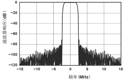
Figure 4 WCDMA filter frequency response
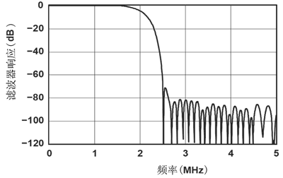
Figure 5 WCDMA filter frequency response transition band width and stop band attenuation relationship
Conclusion
The hardware platform has been successfully applied to a variety of repeater equipment, all of which have reached the corresponding mobile communication repeater standards, with stable and reliable performance and good economic benefits.
Our 12v battery pack designed to be chargeable via motorcycle/car cigaretter, capacity range from 2200mah to 10Ah, with wireless heat controller or bluetooth control. Applications widely ranges in heating clothing, heated motorcycle clothing, heated jacket, electric jacket, electric heated clothing, heated coat, heated vest, heated pants, heatgear, electric gloves, heated jacket mens, heated jacket womens.
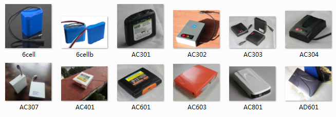
12V Heated Jacket Battery,Heated Jacket Battery, Heated Coat Battery,Heated Vest Battery
Asarke Industry Co., Limited , https://www.asarke-industry.com