Abstract: The tire pressure monitoring of mine vehicles is based on non-destructive testing technology. By studying the real-time signal of tire pressure of vehicles, the variation characteristics of tire pressure of mine vehicles are understood, so as to provide the basis for mine vehicle safety monitoring. A study of a monitoring device for tire pressure composed of LPC2132 as a core is described . The vehicle tire pressure signal is collected by the sensor module with Bluetooth , and after the conditioning circuit is compared, the alarm is calculated, and if the value exceeds the specified value, the alarm is sent and the data is sent to the on-board CAN bus. Based on this, a set of Bluetooth-based tire pressure monitoring device is designed. The hardware system is mainly composed of sensor, LPC2132 processor, signal conditioning circuit, Bluetooth module and alarm module. The software system consists of a firmware program, a data transceiver module, and the like.
This article refers to the address: http://
The development of the automotive industry and the importance people attach to the vehicle safety assurance system have made the automobile tire pressure monitoring system have a large market. Therefore, the mining vehicle company has also started to study this technology.
Among the many factors that affect tire performance, tire pressure is an extremely important parameter. It has an important influence on the bearing performance, high speed performance, braking performance, anti-slip performance, durability and blast resistance of the tire.
1 Scheme for mine vehicle tire pressure monitoring system
Mine vehicle tire pressure monitoring system is mainly used to monitor tire pressure in real time during vehicle driving, and alarms tire leakage and high and low air pressure to ensure driving safety. The pressure of the tire is directly measured by a lithium battery-powered pressure sensor installed in each tire and transmitted to the CAN bus via the Bluetooth module. When the tire pressure is too low, leakage, too high, the temperature is too high or the pressure of each tire is not balanced, the system will automatically alarm, as shown in Figure 1.
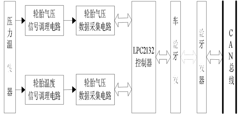
Figure 1 Block diagram of the tire pressure monitoring system
The function of the mine vehicle tire pressure monitoring system is as follows:
(1) Real-time monitoring of the pressure and temperature of a tire; (2) Setting the upper and lower limits of the pressure temperature alarm of each tire; (3) Judging the working condition of each tire.
In general, the tire pressure monitoring system is a low-power mode. At regular intervals, the tire pressure monitoring system is activated by the low-frequency activated Bluetooth transceiver and then enters the normal working mode, and then the tire pressure and temperature are performed. Data acquisition, the data is transmitted as a Bluetooth signal. If the received measurement data exceeds the set standard range, the tire pressure is adjusted by the electromagnetic relay control solenoid valve according to a specific algorithm to realize the automatic charge and discharge function.
At the same time, when the tire pressure is too low, too high or the temperature is too high, the system will automatically alarm.
2 hardware circuit
2.1 Sensor
In general, mining vehicles require 6-12 tire pressure monitoring system modules. In order to improve the system's receiving ability and anti-interference ability, we use MPXY8020A pressure temperature sensor, LPC2132 processor, Bluetooth wireless transceiver module and other major system solutions, the block diagram shown in Figure 2.
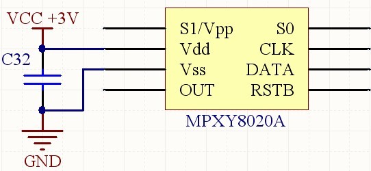
Figure 2 MPXY8020A sensor interface diagram
2.2 LPC2132 Master
The LPC2132 master is based on a 32ARM7TDMI-S CPU that supports real-time emulation and embedded trace with 64k of embedded high-speed flash memory. The 128-bit wide memory interface and unique acceleration structure allow 32-bit code to run at maximum clock rates. Multiple 32-bit timers, 1 or 2 10-bit 8-channel ADCs, 10-bit DACs, PWM channels, 47 GPIOs, and 9 edge or level-triggered external interrupts make them suitable for this system.
As shown in Figure 3.
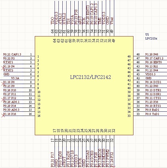
Figure 3 LPC2132 master chip
The LPC2132 main controller mainly works:
a. The data acquisition module communicates and converts and stores the collected pressure and temperature values.
b. Communicate with the Bluetooth transceiver module and send the data to the CAN bus via Bluetooth.
2.3 Signal Conditioning Circuit
The LPC2132 controller's interrupt pin allows the LPC2132 controller to control the A/D converter to keep the input signal synchronized simultaneously. The voltage signal can be programmed by the LPC2132 controller according to the range of voltage signals to be collected, and the voltage does not exceed 3.3V .
In order to make the voltage signal meet the effective acquisition interval of the LPC2132 controller development board, it is necessary to step down the voltage to be collected, and add a Zener tube at the output end of the conversion circuit for protection, as shown in Figure 4.
Considering that the transmission cannot be attenuated and transmitted to the original signal, high-resistance voltage divider can be used for the input. The circuit uses two 3K resistors to divide the voltage. The detection interface circuit shunt is less than 0.5mA, and the sensor incoming signal current is more than 100mA. Ignore, and the back end uses op amp isolation to follow the access, reducing the interference to the tire pressure monitoring system.
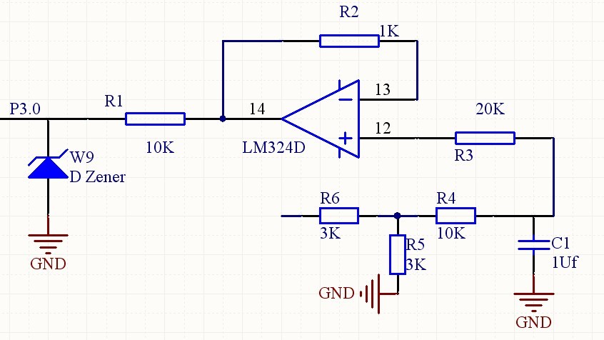
Figure 4 voltage signal acquisition circuit
Figure 5 is a signal conditioning circuit diagram. The purpose of signal conditioning is to amplify and boost the signal from the sensor and send it to the AD module.
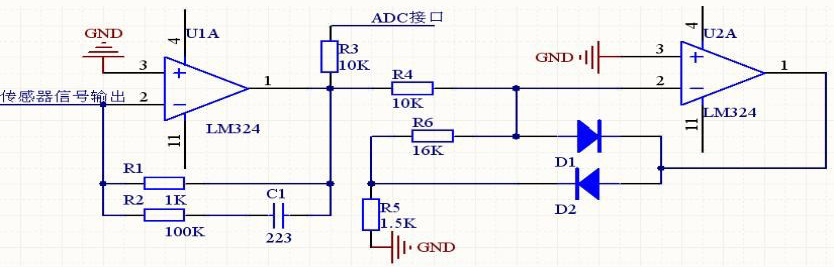
Figure 5 signal conditioning circuit
2.4 Bluetooth transceiver module
The frequency band is designed to be 2.40GHz-2.48GHz, the Bluetooth protocol is BlueTooth V1.2. The hardware uses CSR's AUDIO-FLASH Bluetooth chip, and the module circuit board is 0.8mm four-layer board. The circuit interface includes USB, SPI programming port, 2 AIO analog interfaces, and 9 digital PIO interfaces. Serial data transmission, maximum baud rate of 1.3Mbps, one-to-one automatic chain building.
The Bluetooth transceiver on the wheel is connected to the LPC2132 controller via USB. When communicating with the USB interface, the Bluetooth module is used as a slave device of the USB to communicate with the LPC2132 controller, and data is transmitted through the bidirectional ports D+ and D-, as shown in Figure 6.
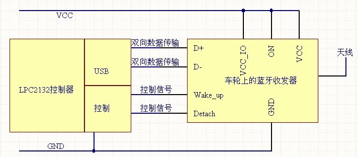
Figure 6 Interface circuit between the LPC2132 controller and the Bluetooth module.
2.5 alarm module
Mainly to complete the display of the state of pressure and temperature, if the set value is exceeded, an automatic alarm.
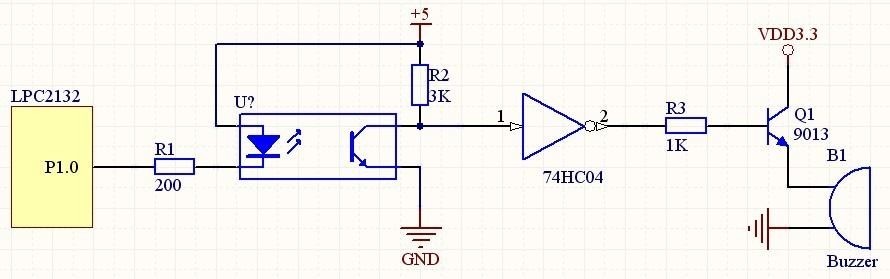
Figure 7 Alarm circuit.
3 software system
The tire pressure monitoring system software corresponds to its hardware and is a function of monitoring the tire pressure with the hardware circuit. The system uses programming software to program KeilC software for embedded systems.
3.1 Main program
When the car is stationary or the speed is small, the measured acceleration a=0. At this time, the KEUP pin of the SPI outputs a high-level wake-up signal. When the car speed becomes larger, the acceleration a>0, then the KEUP pin is every 6 A pulse is output to the LPC2132 processor in seconds to wake the processor into operation.
Two counters are set in the LPC2132 processor. Each time the interrupt is caused by the KEUP pin, the LPC2132 processor performs two rounds of data acquisition on the SPI, which is counted by the counter 2 after the delay. In this case, the LPC2132 processor wakes up 5 times for data transmission, which means that data is sent every 30s.
If the pressure or temperature exceeds the normal range, the delay is 10ms, and the variable i+1 used to control the number of detections is re-tested. The detection is repeated 3 times. If the temperature and pressure values ​​are abnormal 3 times. Then, the temperature and pressure are accurately sampled, a data frame is generated, and a data frame is transmitted. Repeated detection can improve the accuracy of the alarm and prevent false alarms. After completing the data measurement, it goes to sleep. As shown in Figures 8 and 9.
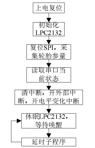
Figure 8 Main program of tire pressure monitoring.
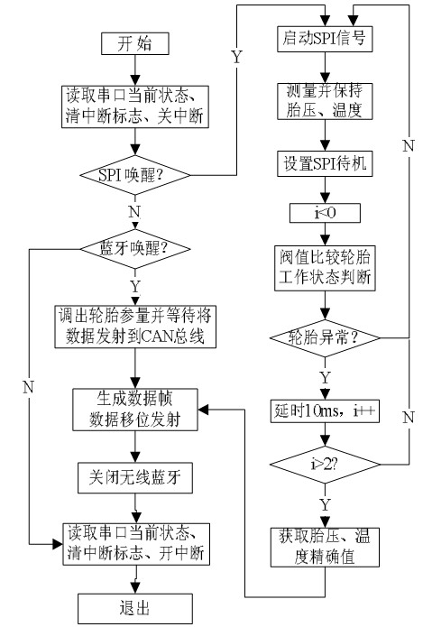
Figure 9 interrupts the server program.
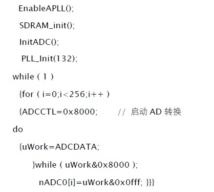
3.2 Implementation of data transmission
Each tire has a corresponding ID. The remote monitoring center needs to detect which tires. It needs to have a corresponding agreement with the tire. For example, the remote monitoring center sends a command first. When the LPC2132 processor receives the command, it needs to Parsing and sending the correct tire data to the CAN bus, the monitoring center will automatically read the data.
This data acquisition uses 256 samples to enable 6-channel cyclic sampling. The first channel sampling procedure is as follows:
3.3 Alarm procedure
The alarm program is an important part of the system. The alarm is divided into pressure alarm and temperature alarm. Each time the system receives the data, it judges according to the preset alarm threshold, as shown in Figure 10.
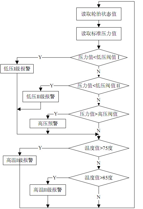
Figure 10 alarm flow chart
4 Experimental data and analysis
The monitoring data produced by the laboratory in the laboratory is measured on the tires of a 6-wheel mine car as shown in Figure 1.
Table 1 Monitoring system test data
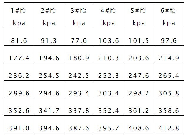
It can be seen from Table 1 that the tire pressure and temperature of the monitored mine vehicles are nonlinear. And when the tire pressure exceeds the standard value (100kpa; 200 kpa; 250 kpa; 300 kpa; 350 kpa; 400 kpa), the alarm is activated.
5 Conclusion
This system is part of the intelligent dispatch system, and the feasibility of the system scheme is illustrated through experiments. This system is the application of embedded technology in mine safety, and it is of great significance for safe production and improvement of production efficiency.
Mic Wireless,Wireless Microphone,Bluetooth Microphone,Condenser Microphone
NINGBO SANCO ELECTRONICS CO., LTD. , https://www.sancobuzzer.com