1 Introduction
In recent years, the number of people engaged in LED manufacturing and R&D has increased significantly. LED companies are also growing like mushrooms. Due to the large number of enterprises and people engaged in the research and development of LED drivers, the technical level of them is uneven, and the quality of LED driver circuits developed is mixed. The failure of LED lamps often occurs, which hinders the frequent promotion of LED lighting. The failure of LED luminaires is due to the failure of the power supply and the drive, and the failure of the LED device itself. This paper tries to analyze the working principle of the circuit from the actual LED power supply circuit, and then tries to analyze the failure effect of various working sensitive parameters from the LED driving circuit under different environments to perform the failure mode. The analysis, finally, verified the results by simulation. And theoretically give a solution to failure.
2. LED drive circuit principle
LED is a kind of semiconductor material made of light-emitting diode, which can only be single-pass, and its conduction voltage is not high, and the forward conduction current can not be too large, so there is a certain requirement for the power supply of LED, then LED The drive circuit came into being. In actual use, most of the LED products use an alternating current power supply as the power input of the LED driving circuit, and the driving circuit becomes a circuit of a regulated output form or a constant current output form. The LED driver circuit can be divided into many types according to different division criteria. At present, according to the driving principle of the circuit, it can be divided into two categories: one is a linear driving circuit, and the other is a switching driving circuit.
2.1 linear drive circuit
The schematic diagram of the linear drive circuit is shown in Figure 1. The structure generally includes the following parts, the rectifier circuit, the filter circuit, and the voltage regulator circuit.

The figure uses full-wave bridge rectification to rectify the alternating power supply into a unidirectional ripple voltage. The filter circuit adopts RC filtering, and the voltage value filtered by the filter circuit is relatively close to the DC power supply. However, due to the voltage fluctuation on the power grid, the output voltage of the driving circuit fluctuates, which is fatal for the LED. Therefore, the voltage after filtering needs to be added with a voltage regulator circuit. So that the linear drive circuit can maintain a relatively smooth voltage to drive the LED.
In a linear drive circuit, the brightness of the LED is a function of the pass current, independent of the voltage drop applied across the LED. As can be seen from the above circuit schematic, the linear LED driver circuit is simple in structure, easy to implement, short in development cycle, low in production cost, small in size, and, because no large-capacity capacitors and inductors are used, circuit design is not required. Consider EMI issues. Can be applied to low current lighting systems.
2.2 Switching drive circuit
The schematic diagram of the switch-type drive circuit is shown in Figure 2. After the input alternating voltage is rectified and filtered by the rectifier circuit, the current or voltage of the LED is controlled by the switch state, so that the LED can illuminate smoothly. A typical switch-type drive circuit is given below to gradually analyze the operating state of the switch-type drive circuit.
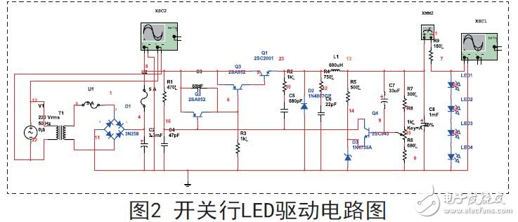
As can be seen from FIG. 2, the switch LED driving circuit can be divided into the following parts: a low frequency rectification filter circuit, a self-oscillation circuit, a voltage stabilization circuit, a sampling pulse width adjustment circuit, and a high frequency rectification filter circuit.
The mains AC 220V is stepped down by a 12V transformer, and then a low-frequency rectifying and filtering circuit is formed by a bridge rectifier diode 3N258 and a capacitor C2, and converted into a DC-like power source. The power transistors Q1, Q2, Q3 and the capacitor C5 resistor R2 form a self-excited oscillation circuit, wherein Q2 is a PNP tube, which is a pulse width adjustment tube, one of Q1 and Q3 is a PNP tube, and one is an NPN tube, and two tubes are combined to form a switch. Adjuster, C5, R2 can set the oscillator frequency by adjusting the parameters. With this self-oscillating circuit, a DC-like power source can be converted into a high-frequency pulse signal. The frequency of the high frequency signal can be calculated by the frequency selection characteristic. The duty cycle of the high frequency pulse can be adjusted to adjust the energy output from the device. When the current flows through the inductor, an induced electromotive force is generated at both ends of L. When the current disappears, the induced electromotive force generates a reverse voltage across the circuit, if the reverse voltage is greater than the reverse breakdown of some components. These voltages will damage these devices. A freewheeling diode D2 is connected in parallel across the inductor, and a loop consisting of R4 and C6 provides a venting loop for this reverse induced electromotive force.
The sampling circuit composed of R 6, R 7 and R 8 and the reference source circuit composed of R 5 and D3 are used for adjusting the pulse width of the high frequency signal to adjust the saturation conduction time of the switching tube, thereby adjusting the output voltage of the power supply. . Among them, R7 is an adjustable resistor to facilitate the adjustment of this voltage.
It can be seen from the above analysis that the switching LED driving circuit has higher efficiency than the linear driving circuit, and the output current is large, and the current can be adjusted by adjusting the pulse width, and the output current precision is very high, so that the LED brightness can be Controlled, suitable for use in large lighting situations and current output.
3. Analysis of LED drive failure mechanism
3.1 LED drive circuit failure analysis
(1) Surge current and surge voltage
Due to the instant of opening of the driving circuit, the capacitor charging requires a large current, and its charging time is short, resulting in a large instantaneous current; due to voltage fluctuations on the power grid and surge voltage, the diode and resistors on the driving circuit are caused. The moment of large voltage. This can cause permanent damage to devices on the LED driver circuit.
(2) Electrostatic discharge
Electrostatic discharge, the ESD phenomenon. Since the electricity is discharged in a very short period of time, the static bleeder voltage can often reach several thousand volts. This is fatal for semiconductor devices. ESD may damage the internal structure of the LED lamp or the driver IC.
LED Linear Light is a kind of high-end flexible decorative lamp, advantages with low power consumption, long life, high brightness, easy to bend, maintenance free and so on.
It is especially suitable for indoor and outdoor entertainment places, building outline and billboard making.
According to different requirements, the product has 12V, 24V, 30CM,60CM, 90CM, 120CM and so on.Line lamps of different specifications can also be customized according to customer requirements.LED Linear Light
Linear Light,Linear Lamp,Led Linear Lighting,Linear Ceiling Light
Jilin Province Wanhe light Co.,Ltd , https://www.wanhelight.com