Executive summary
With the increasing complexity of today's industrial control systems, there is now a need for a more intelligent motion control system to replace the control system where all control-driven tasks were completed by a central control system. The control system can well reduce the complexity of the system control, improve the flexibility of the motion control system, and have a good performance in reducing costs and improving the stability of the motion control system. This article will mainly introduce the production of CAN based on Taiwan's production Bus products realize the design and development of a distributed motion control platform.
Keywords: servo system; CAN; distributed motion control; PAC
Foreword
Servo system (servo system), also known as servo system, is a kind of automatic control system. It is used to control the rotational angle (or displacement) of the controlled object, so that it can automatically, continuously and accurately rewrite input instructions. The law of change. It is usually a closed-loop control system with negative feedback. In some cases, open-loop control can be used to achieve its function. In practical applications, the automatic control system is generally controlled by a mechanical position or an angle, such as a numerical control machine tool. The drive motor used in the servo system has the characteristics of fast response, accurate positioning and large moment of inertia. This type of special motor is called a servo motor. Distributed servo system based on CAN bus Multi-motor servo control is widely used in various electric drive automatic control systems, such as batching, transmission and other production processes. The motor control performance in the servo system and the coordinated control of multiple motors directly affect the quality of the production process. How to efficiently manage, facilitate application, and real-time control is the most important issue to be solved in the production field of multi-motor servo systems. The CAN bus technology solves many problems of the traditional bus board I/O modules, serious interference, complicated system software programming, and poor system hardware compatibility. It greatly reduces the complexity and cost of on-site signal connections, improves the precision and flexibility of signal transmission, and brings convenience to installation, commissioning and maintenance. It brings huge economic benefits to on-site users and represents an important development in the field of automation. direction.
I. Introduction to CAN bus distributed servo system
With the continuous advancement of industrial field control and automation technology, the traditional communication mode can no longer meet the needs of modern engineering. The CAN (Controller Area Network) bus is a serial data communication protocol developed by Bosch in Germany in the early 1980s to solve the data exchange between many control and test instruments in modern automobiles. It is a kind of advanced performance, low price, and good confidentiality. Fieldbus technology can effectively support distributed control or real-time control of serial communication networks. Each node in the CAN bus has the right to send information to other nodes. The communication medium can be twisted pair, coaxial cable or optical fiber. The main technical features are: a multi-master bus: any node on the network can actively send information to other nodes on the network at any time. The multi-master station is based on the priority mechanism. Bus access; Non-destructive priority-based bus arbitration technology: The use of non-destructive priority-based bus arbitration technology structure, greatly reducing the bus conflict arbitration time, showing good performance under heavy load; has a variety of data transmission functions: Peer-to-peer, point-to-multipoint (group) and global broadcast transmission data functions; number of nodes: direct communication distance up to 10km (transmission rate of 5kbps), maximum communication rate up to 1Mbps (transmission distance of 40m); reliable High: Data link layer adopts short frame structure, high real-time performance, good error correction effect, CRC check and other verification measures for each frame of information, low data error rate, high reliability; automatic fault identification: during transmission If the arbitration is lost or the frame that has been corrupted due to an error is automatically retransmitted, the temporary fault and permanent fault node identification and faulty node are automatically disconnected from the CAN bus. The CAN bus system consists of CAN network nodes, repeater nodes and host computers. The bus technology follows the fieldbus protocol and will be distributed in different locations, measuring instruments and control devices with different uses and interconnected into a network, and can be connected to Intranet and Internet networks. The key sign of fieldbus technology is that it can support bidirectional multivariable, bus-type full digital communications. The traditional 4-20mA analog DC loop can only transmit one parameter in a single two-core cable. With the increasing complexity of the system structure and the increase of the amount of information, the 4-20mA current loop transmission becomes a bottleneck for information transmission, so the scene Bus replacement of the 4-20mA analog signal standard has become an inevitable trend in the development of control systems.
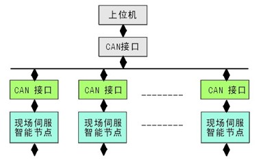
Figure 1 CAN bus network structure
Based on the CAN bus technology of multi-motor servo control system network structure shown in Figure 1, the system consists of host computer, CAN bus, field servo unit node. The upper computer of the numerical control system controls any servo unit of the network node through the CAN bus. The data transmission between the digital servo and the numerical control system can be divided into real-time data information and non-real-time data information. Real-time data refers to the controller's real-time position, speed, torque and other control instructions and feedback information, and the transmission speed is required to be high. Non-real-time data mainly refers to controller parameter settings, function settings, diagnostic functions, servo status and alarms, etc. The transmission speed is relatively low. The CAN interface adapter is the bridge for data transmission and control between the host computer and the servo unit. The data collected by the servo unit is transmitted to the host computer through the bus to realize real-time monitoring and control.
Second, module introduction
I-87120 is one of CAN series products produced by ICP DAS in Taiwan and supports CAN2.0A/CAN2.0B protocol. It has 1 CAN port and built-in 80MHz CPU. The specific specifications are as follows:

The I-87120 cannot be used alone. It needs to be used with the PAC produced by ICP DAS. The corresponding SDKs are provided for different PACs. At the same time, with PAC's powerful processing capabilities, data display, transmission, and storage functions can be easily implemented, greatly enriching distribution. The function of the servo system can complete the design requirements for complex data machines.
Fourth, the conclusion
CAN bus has good network communication function, high reliability, strong anti-interference ability and economical and practical. It is a promising field bus technology. Its application will provide a new solution for distributed servo systems, which will receive more and more attention from people. The new generation of intelligent digital servo system interconnects with the open CNC system through the CAN bus. It is a promising direction for the development of distributed servo systems.