Fault self-diagnosis, when the control system fails, the main ECU (Electronic Control Unit) will light the “CHECK†lamp on the dashboard to remind the driver that the engine has malfunctioned and the fault information The form of the fault code is stored in the ECU. Through certain procedures, the fault code and related information can be retrieved for maintenance.
1. Self-diagnosis system working principle · Roewe sells 218,800 pieces · Dongfeng Peugeot reduces 22,000 · Pentium manual gear is listed in June · Non-normal input and output signals detected by self-diagnosis For the fault signal, the main faults of the self-diagnosis system are as follows.
1. When a signal in a circuit exceeds the specified range, the fault diagnosis system determines that the circuit signal has failed.
If the water temperature sensor is normal, the output voltage signal changes in the range of 0.1-4.8V. If the cooling water temperature sensor output voltage is lower than 0.1V (equivalent to a water temperature higher than 139°C) or higher than 4.8V (equivalent to a water temperature lower than -50°C), the ECU judges that the fault signal is stored in the memory.
2. When the engine is running, when the ECU does not receive the input signal or the input signal of a certain sensor for a certain period of time, the ECU also determines that it is a fault signal.
If the engine is running at normal operating temperature, the ECU does not detect the output signal of the oxygen sensor more than one minute or the oxygen sensor signal does not change between 0.3-0.6V for more than 1 minute, ie it is determined that the oxygen sensor circuit is faulty.
3. In the normal operation of the engine, if an accidental signal occurs occasionally, the ECU diagnostic system will not judge the fault. Only when the abnormal signal lasts for a certain time or multiple times, the ECU will judge it as a fault. If the engine speed is 1000r/min, the speed signal (Ne signal) will lose 3-4 pulse signal, and the ECU will not judge it as Ne signal failure, at the same time, "CHECK" light will not light, Ne signal failure will not be stored in the ECU.
It should be noted that the fault identified by the ECU can only provide the nature and scope of the fault. If the wiring between the water temperature sensor and the ECU is disconnected, the output voltage signal of the water temperature sensor will be higher than 4.8V (normally 0. l-4.8 V). At this time, the fault information determined and output by the ECU is a fault of the water temperature sensor. The final determination is the failure of the sensor, actuator or corresponding wiring. It should be further examined and confirmed.
Second, the fault information display method ECU fault self-diagnosis system detects the fault signal After the fault is determined, that is, fault information in the form of fault code stored in the ECU memory. Through a certain operating procedure, the fault code or fault data is displayed in a specific manner. Different types of fault information are displayed in different ways. There are mainly the following children:
1, by the CHECK (check engine) flashing fault code.
When the engine is operating normally without fault, turn on the ignition switch to the "ON" position and the "CHECK" lamp lights up. The lamp should be extinguished when the speed is higher than 500r/min after the engine is started. Otherwise, if fault occurs, the fault code can be displayed in a flashing manner of the “CHECK†lamp by using a dedicated jumper across the diagnostic socket or through other operations. After troubleshooting, the "CHECK" light extinguishes when the engine speed is higher than 500r/min.
2. Use LED (faulty display) lamp to bridge fault diagnosis output terminal of diagnosis seat, or cross-connection special detection instrument, such as percentage table, angle-closing table, computer tester, etc. to directly read fault code or fault information data.
3. The fault code is displayed on the side display lamp of the main computer ECU.
4, from the dashboard display directly displays the fault code, information and data.
Third, the fault information clear After troubleshooting, the fault information is still stored in the ECU can not be automatically removed with the removal of the fault must be through the operating procedures. Different methods of vehicle removal are also slightly different. The general method of removal is to remove the "EFI" fuse from the fuse box for more than a few seconds, but there are exceptions.
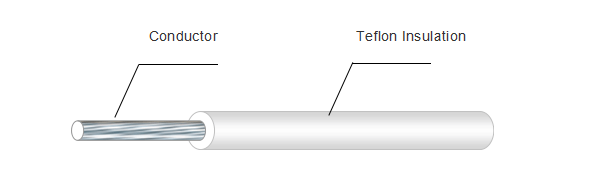
Teflon Insulated Wires and Cables is a HEAT RESISTANT CABLE which including Fep insulated wires and cables, PFA insulated wires and cables, PTFE insulated wires and cables.. Teflon Wires and Cables is one of our most popular offerings. FEP, PFA or PTFE extruding insulation is a high performance alternative to standard polyethylene insulation. A Flexible Teflon Insulated Wires and Cables will not only have superior insulation characteristics, the higher melting point of teflon make it ideal for high voltage uses and other extreme applications. Yangzhou Fongming Cable Factory gained UL certificate for the teflon insulated wire and cable including high voltage special wire, like AWM1330, AWM1331, AWM1332.
Structure:
Conductor: Tinned copper stranded.
Insulation: FEP insulated, PFA insulated, PTFE insulated.
Color: Black, white, yellow, blue, red, green, yellow/green and can be customized.
Rated voltage: 300V, 600V
Rated temperature range: -40℃~+150℃, 200℃
Standard: UL758, UL1581
Typical application: They are widely used in variety of lighting appliances, household appliances, temperature sensors, electronic devices, etc..
Size
(AWG)
Conductor
Structure
(mm)
Insulation Thickness
AVG(mm)
Insulation Thickness
Min(mm)
Diameter
MAX.COND Resistance
(Ω/Km@ 20℃)
Unit Length
(M)
26
7/0.16
0.51
0.46
1.50±0.10
153
610
24
7/0.20
1.65±0.10
95.8
610
22
7/0.254
1.80±0.10
60.7
610
20
7/0.320
2.00±0.10
38.1
305
18
7/0.39
2.25±0.10
23.9
305
16
19/0.30
2.60±0.10
15.0
305
14
19/0.38
3.00±0.10
9.42
305
12
19/0.48
3.50±0.10
5.88
305
FAQ:
1. Why the price is so low?
2.Where is your factory located? How can I visit there?
3.Can I get some samples?
4. Can you make the products with my design?
Yes. customization is welcome .
You are ordering directly from the factory.
Our factory is located in Yangzhou City, Jiangsu Province, China,which is near Shanghai. All our clients, from home or abroad, are warmly welcomed to visit us.
Yes, we are honored to offer you samples.
Teflon Wire,Teflon Insulated Wire,Fep Insulated Wire,Pfa Insulated Wire
Yangzhou Fongming Cable Factory , http://www.hightemperaturewire.com