1 Introduction
This article refers to the address: http://
At present, the distributed control system (DCS) has been widely used in industrial control fields such as petroleum, chemical, electric power, and metallurgy. In the actual engineering application of DCS, it is usually necessary to design a specific control scheme according to different control objects, and then implement it by means of control configuration on the DCS. However, due to the limitations of actual engineering, it is difficult for newly designed control strategies and algorithms to have the opportunity to test on site. Therefore, it is necessary to design a simulation model of the controlled object for use in DCS testing.
In recent years, MATLAB has emerged as a powerful and widely used software in the field of control. It can be used to easily build simulation models for various controlled objects. If DCS and MATLAB can be connected, and the control operation function is completed by DCS, MATLAB provides the simulation model of the controlled object. It will give full play to the advantages of both, and it will also greatly help researchers develop new control strategies and algorithms.
Taking the tracked vehicle transmission system as an example, this paper builds a vehicle transmission system simulation platform based on Guodian Zhishen's EDPF-NT system and MATLAB. On this platform, the vehicle drive system electronic control simulator was developed in the EDPF-NT system to control the operation of the drive system. Use MATLAB to build a drivetrain model that simulates the operation of the drive train. The platform can easily simulate the shifting process of the transmission system, and provide a better simulation environment for optimizing the shifting strategy and improving the overall performance of the transmission system. The overall structure of the simulation platform is shown in Figure 1.
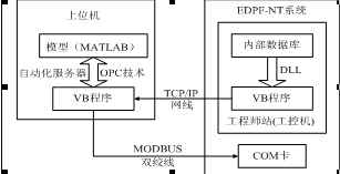
Figure 1 shows the overall structure of the simulation platform
2 simulation platform hardware components
When building a drivetrain simulation platform, you must first solve the hardware design problem. It is mainly composed of the engineering station of EDPF-NT system, DPU card, COM card, I/O card and host computer. The function of the engineering station is to carry out the configuration and design control scheme, while the upper computer mainly runs the MATLAB model of the transmission system and the data communication program.
3 simulation platform data communication implementation
In the process of constructing the transmission system simulation platform, the fast and accurate communication of data in the platform is the key research content, which mainly solves the data communication between EDPF-NT system and MATLAB. For security reasons, the database of EDPF-NT system only allows reading and not allowing writing, so the data communication between EDPF-NT system and MATLAB model is realized in three parts. First, read EDPF-NT at the engineering station. The system real-time data is sent to the host computer, followed by the MATLAB model to read the EDPF-NT system data sent to the host computer. Finally, the data after the MATLAB model is run is sent to the EDPF-NT system through the COM card in the host computer.
3.1EDPF-NT system data reading
The data of the EDPF-NT system is stored in the database in a specific format and cannot be directly read or written. In order to facilitate the user's use of data, Guodian Zhishen provides NTClient.dll file that can be called by VC, VB and other software. Users can read the real-time data of EDPF-NT system through the function provided by NTClient.dll. This article uses VB to develop a program that reads EDPF-NT system data and uses the Winsock control to send the read data to the host computer. This program is divided into three parts:
1) Declare the function provided by NTClient.dll;
2) Read the data of the EDPF-NT system;
3) Send data to the host computer.
3.2 MATLAB call to EDPF-NT data
As the most popular simulation software, MATLAB plays an important role in the analysis and design of control systems. However, MATLAB itself does not provide an underlying communication interface, and other methods must be used to implement data communication over the network. Therefore, the data sent to the host computer by the EDPF-NT system engineer station is first received by the program written by VB, and then the call to the data is realized by the OPC technology.
When transferring data between different programs, it is necessary to select a suitable communication interface. For this reason, the software interface standard OPC (OLE for Process Contro1) technology of the industrial control industry is introduced. OPC technology tries to solve the problem of data exchange between different programs and devices according to the standard method. It adopts the server/client mode. As long as a server with a unified OPC interface is provided, the server can be accessed according to the consistent OPC client interface. Data exchange.
MATLAB can be used as an ActiveX automation controller. With ActiveX automation controller technology, users can control the ActiveX automation server by writing M files in MATLAB. Using VB to develop the OPCAxtiveX control using OPC automation interface, add the communication module in the OPCAxtiveX control, receive the data of the EDPF-NT system, and assign the data to the attribute value of the OPCAxtiveX control, and obtain the corresponding attribute value in the OPCAxtiveX control through MATLAB. It is possible to implement MATLAB's call to EDPF-NT system data under OPC technology.
The first is to create an OPCAxtiveX control and set up the network in the initialization of internal working variables. Secondly, the network communication code is added in the OPCAxtiveX program, and the data sent to the upper computer by the EDPF-NT system engineer station is received. Finally, the received data is assigned to the ActiveX control property value, the OPCAxtiveX control is generated, and registered. The OPCAxtiveX control for data reception can be used by MATLAB.
Before using an ActiveX component in MATLAB, you must find the name of the object, ProglD, and also the methods, properties, and events used by the object. With this information, this object can be applied in MATLAB via ActiveX customer support.
Use the actxcontrol function to generate an ActiveX component that enables communication between MATLAB and OPC.
The syntax for generating an ActiveX component in the graphics window is:
h=actxcontro1(progid[,position[,handle···[,callback{event1eventhander1;···event2eventhandler2;}]]])
Use the get, set, invoke, propedit, release, and delete functions to manipulate the OPCAxtiveX control, and finally implement MATLAB's call to EDPF-NT data.
3.3EDPF-NT system data input implementation
As mentioned earlier, for security reasons, the data in the EDPF-NT system database is only allowed to be read and cannot be directly written. Therefore, the data from the MATLAB model must be sent to the EDPF-NT system via the COM card using the Modbus protocol. Using the ModbusMaster communication control in VB, it is convenient to send data to the Modbus Slave (COM card).
When transmitting data to the EDPF-NT system, you need to set the corresponding communication parameters, including port, baud rate, response timeout, data bit format (RTU/ASCII), check mode, stop bit, and COM card related. Slave address and the physical start address of COM when sending data.
After each run of the MATLAB model, the data is automatically sent to the COM card of the EDPF-NT system via the Modbus network. The EDPF-NT system will read the data sent to the COM card.
4 data communication test
After the software and hardware debugging is completed, the manual data shift is taken as an example to test whether the data communication of the platform is accurate and reliable. First, the platform is in operation and controlled on the drive electronic control simulator developed by the EDPF-NT system. The operation interface of the electronic control simulator is shown in Figure 3.
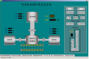
Figure 3 electronic control simulator operation interface
The control signal of the EDPF-NT system can be quickly sent to the transmission system model in the host computer to control the operation of the model. At the same time, the host computer sends the data obtained after the model is run back to the EDPF-NT system, and in the electronic control simulator. Displayed on the interface.
During the test, the operation is performed on the electronic control simulator, and the gear is changed from the first gear to the fourth gear. The transmission system model located in the upper computer receives the shift control signal and runs according to the given gear position. The output speed curve of the transmission system obtained after the operation is shown in Fig. 4.
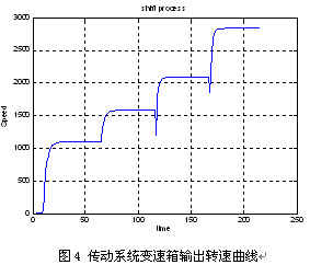
Through the test, it can be seen that the data communication in the simulation platform is fast, accurate and reliable, and can meet the requirements of the simulation experiment.
5 Conclusion
This paper provides a relatively complete solution to the problem that the data between different devices and software cannot be shared in the vehicle drive system simulation platform based on Guodian Zhishen EDPF-NT system and MATLAB, and realizes the data communication in the whole platform. The simulation platform works well and the data communication is accurate and rapid, which provides help for the research of vehicle transmission system.
Nh Fuse And Base,Low Voltage Fuse,Ceramic Fuse Base,Nt Fuse And Base
Tengqiang Electronics Co.Ltd , http://www.xingdaele.com