In the early stages of development, a hardware-in-the-loop (HIL) test environment was developed to test the drone GNC solution. The HIL test environment is an intermediate step in software simulation and aircraft experiments and is critical to the development of drone GNC software. Through the HIL environment, engineers can test drone software in a controlled simulation environment. At the same time, it can speed up the design and shorten the development cycle. Through the HIL environment, engineers can detect problems that are not present in software simulation (mainly synchronization and timing), thus avoiding field test failures and increasing the safety of the drone team. . A generic HIL platform was developed to design verification control and navigation algorithms. This HIL test environment is fully integrated into a model-based design development cycle (see Figure 1).
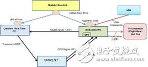
Figure 1: Schematic diagram of the HWIL test environment
Model-based development
First we designed and modified the drone platform, used it for simulation, and deployed the controllers and algorithms into the hardware. This task is done according to a model-based design philosophy. This is a reliable and convenient method for system design and simulation. Using code auto-generation tools allows us to reduce design time, easily re-use test architectures, and quickly prototype the system to form a continuous validation and verification process.
The purpose of the architecture includes: reusing the model without any changes on different hardware platforms; reusing the design test suite model to verify the target system; fully integrating the transparent model into the target hardware and creating a system, A fast process that integrates automatically generated code into the target hardware so that the control engineer can quickly test the model without the involvement of a software engineer (see Figure 2). For this project, model tasks were developed using Simulink®'s MathWorks software (we also used Esterel Technologies' SCADE kit) and automated coding was performed using MathWorks and Real-TIme Workshop® software. Two different edits are required: the algorithm for testing and executing in the drone is written in ANSI C code. The mathematical model for simulating the dynamic behavior of the drone will be converted to the NI LabVIEW software dynamic library through the LabVIEW Simulation Interface Toolkit. in.
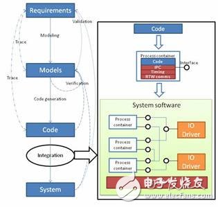
Figure 2: Model-based development process
In the final system, we used multiple LabVIEW I/O modules to simulate some of the drone avionics and logic sensors and actuator interfaces.
LabVIEW Real-TIme PXI
PXI is a PC-based platform for test, measurement and control that provides high bandwidth and ultra-low execution latency across different interfaces and buses. In this case, PXI needs to run in a complex drone model that will be executed as a dynamic library in real time. Using a PXI module in the system allows us to perform HIL simulation using the exact same interface on the drone. Therefore, we will verify the GNC algorithm processing unit with the exact same configuration of the field experiment. This is important for systems that use pure emulation to capture all hardware-related issues such as signal noise, errors, and synchronization issues. With the Spirent GSS8000 GPS Simulator, we were able to simulate and generate the same RF signal from the user-selected GNSS constellation satellite. These signals are transmitted to the real GPS sensor on the drone in the same way as the flight test, and can simulate inertial sensors (accelerometers and gyroscopes). You can specify different conditions, degrade the signal, specify the antenna mode and simulate the IMU sensor error.
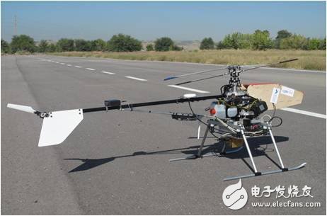
Figure 3: The drone based on the CB5000 RC helicopter used in the experiment
Onboard processing unit
Running a PC/104 unit in a real-time operating system (QNX or VxWorks), the operating system contains algorithms and control strategies for testing the completion of code created by the automated code generation tools and integration architecture. We used the same unit in the real drone that we experimented with in the field. We can use the Simulink External Mode software to debug the drone. With this software, we can monitor the signal values ​​that users need to know in real time. In addition we can change the parameters of the algorithm executed in the embedded processing unit. The interface used in the operation is exactly the same as the interface used by the control engineer to simulate the design algorithm. As a result, the entire test environment is completely transparent and HIL testing can be performed in the same way as field testing, dramatically reducing development time.
Comparing flight telemetry with HIL simulation using the same GNC algorithm, it can show the accuracy of HIL and the similarity with real test results. Several sensors (accelerometer, gyroscope, magnetometer, GPS and an altimeter) and a processing unit (see Figure 3) are integrated on a modified radio-controlled helicopter to turn it into an unmanned Machine, flight test. The drone reaches the reference value required by the horizontal plane without overshoot or any permanent error (see Figures 4 and 5). The HIL simulation is extremely consistent with the actual flight test results.
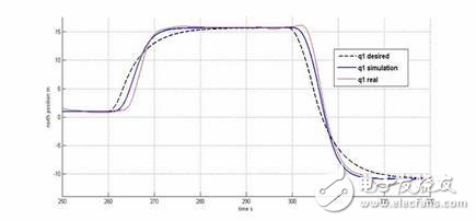
Figure 4: North position comparison results
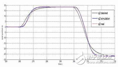
Figure 5: Western location comparison results
The HIL environment is ideal for testing entire systems with real hardware. With NI PXI, we simulated a complex drone model with low latency in real-time and perfectly simulated the aerospace interface. This environment can detect errors that cannot be displayed in the software simulation, thus avoiding accidents in the field. Because control engineers use the same visualization and debugging tools during design, development, and verification, they can cycle quickly and reduce development time.
Precautions before installation:
1.Please check the
appearance of the iPhone 8 Plus 5.5" LCD Screen carefully when receive
it to confirm whether there is appearance breakage. Any problems, Please
do not hesitate to contact us and provide photos for the problem.
2.Please
make sure you are a special repair technician, because it is not an
easy job to repair the screen (especial the flex ribbon is easy
fracture), please test the item firstly before installing it, just by
plugging the flex cable to your mainboard, we will not be responsible
for any faulty or damaged after the assembly.
3.There are
different sizes and length screws when you replace your iPhone LCD
Assembly, please remark each screw and put them in the original place.
Otherwise the screen will be easy broken if you put the screw in the
wrong place.
Test:
· On-off flex cable;
· Flash;
· Charging Port & Charging flex cable ;
· Back camera;
· Volume button;
· Mute button;
· Buzzer & Vibrator;
Features:
· 12 Months warranty.
· Flex cables are all original.
· Exquisite craftsmanship.
· Inner Package: Anti-Static Bags & Transparent Air Bubble Bags ; Outer Package: Carton Box Also In Lined With Foam;
iPhone 8/8 Plus Housing Assembly
iPhone 8 Plus Back Cover,iPhone 8 Plus Back Cover Housing,iPhone 8 Plus Housing Assembly
Shenzhen Aokal Technology Co., Ltd. , https://www.aokal.com