0 Introduction Video-based vehicle detection technology is developed on the basis of traditional TV surveillance systems, based on vehicle detection technology, cameras and computer image processing technology, to implement a wide range of emerging technologies for vehicle detection and recognition. Compared with traditional detection technology, it has many advantages such as fast processing speed, convenient installation and maintenance, low cost, wide monitoring range, and access to various traffic parameters. With the development of image processing technology and microelectronic technology, the development potential of video detection technology in transportation system is huge.
In a typical traffic automatic monitoring system, a static camera is used to monitor a fixed area in real time, and the traffic parameters are further extracted through operations such as the extraction, classification, and tracking of vehicle targets. Therefore, real-time segmentation of vehicle targets from the video stream is a basic link of the automatic traffic monitoring system. The process of extracting vehicle targets mainly includes using an algorithm to extract the foreground vehicle from the captured image, and performing shadow detection to remove the shadow. According to this process, this paper selects a suitable foreground extraction algorithm-background difference method, updates the background in real time, analyzes the shadows generated in the foreground, and proposes a reasonable and effective method for removing shadows.
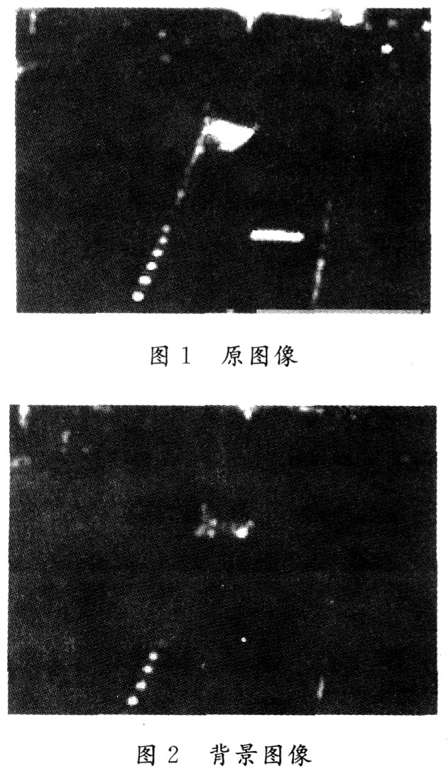
l Video-based vehicle detection Background difference method is a commonly used algorithm in vehicle motion detection system. This algorithm can obtain a foreground image by maintaining a background model in real time and removing the current frame from the background. The roads, trees, buildings, etc. are always in a static state, so they are removed as differences by the background. The processed image theoretically only includes moving targets, directly binarizes and extracts the target, but in fact at this time, due to camera shake and changes in road light, wind and grass, shadows of the vehicle target itself and other factors, the detection results The impact is great, often causing great errors, or even errors. After extracting the foreground, aim at different shadows and remove them to obtain real vehicle targets.
1.1 Background modeling Use the first n frames of image for background modeling (using n = 200). Make a difference between two adjacent images at a certain interval to obtain a difference image A. There are:
In the formula: N is the difference of the corresponding position of A, and the binary frame difference mask image N is obtained; "1" is the pixel corresponding to change; "O" is the pixel corresponding to no change.
In the frame difference mask sequence, for a pixel point that has not changed for a long time, that is, the pixel point of the frame difference mask image sequence remains "O" for a period of time, it is considered that this pixel point corresponds to the background pixel, and the original The pixel value of this point in the image is copied to the ideal background image, and the state of this ideal background pixel is set to "background pixel". After this process is completed, the state of some ideal background pixels may not be converted into "background pixels", that is, they have not been reconstructed. In the subsequent process, the above steps are continued, and the reconstructed background pixels are switched to the background. Update.
1.2 Background update After the background image is obtained, there will be many changes in the scene with the passage of time. Among them, the changes in the brightness of the light and the movement of the background objects are more obvious. In this paper, a method of weighting the current image and the background image is used for updating. The update method is: remember that the pixel value in the current image is I (x, y), the pixel value in the background image is I * (x, y), the corresponding frame difference mask image N (x, y) = 0, then I (x, y) is the background pixel, and I (x, y) and I * (x, y) are weighted according to equation (2): ![]()
In the formula: α is the update coefficient, which is related to the update speed, and the update speed requires the background to capture the change in brightness, and at the same time, it cannot allow the instantaneous change to exist for a long time. Assume that α = O. 1. When the brightness of the image changes over a large area, the average value of the entire background pixel will change significantly, so when the average value changes greater than a certain range, in order to be able to update the background faster, take α = 0.2.2.
If | I (x, y) -I * (x, y) | is greater than the threshold or N (x, y) = 1, then I (x, y) is the foreground pixel; if I (x, y) is continuous for a long time As a foreground pixel, the background of this pixel needs to be reconstructed, and the background is restored again according to the background reconstruction steps.
1.3 Extraction of moving target After obtaining the reconstructed background, the moving target can be obtained according to the difference between the current image and the background image. In order to reduce the amount of calculation and interference, the region of interest can be set in advance, and subsequent processing is only performed in the region of interest. Let the video sequence image be I (x, y), the current background image is I * (x, y), and the background difference image D (x, y) = || I (x, y) -I * (x, y) ) ||. Use the threshold to calculate the vehicle image pixel template image:
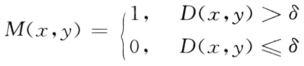
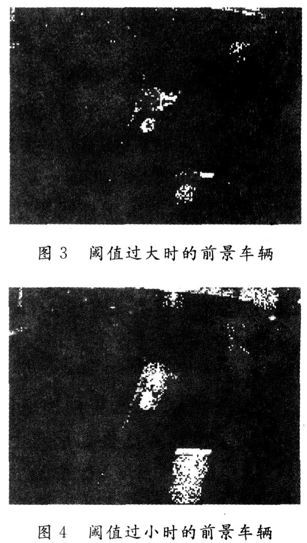
In the formula: δ is a small threshold, the point 1 in the template image M (x, y) indicates the vehicle image area, and the point 0 is the background image area. The vehicle information obtained by simply using the difference in gray value is incomplete: if the threshold is too large, some parts of the vehicle will be considered as the background, making the vehicle image incomplete, the information obtained from the vehicle is inaccurate, and even the shadow part The information of the vehicle has not been eliminated, but the information of the vehicle part has been largely eliminated (see Figure 3); if the threshold is selected too small, the shadow formed by the light will be connected to the vehicle and become part of the vehicle (see Figure 4), but this method can well retain the complete information of the vehicle, as long as the interference of the shadow part can be eliminated, a good effect can be achieved. Therefore, removing shadows accurately plays a key role in the process of extracting vehicle information.
2 Shadow detection and elimination Moving vehicles and road objects inevitably produce shadows under the influence of light. The shadow of the stationary object can be removed by background difference, but due to the camera shake, the re-movement of the stationary object, etc., the shadow part cannot be completely removed to generate noise (hereinafter referred to as the outer shadow); the shadow of the target vehicle itself and the projection between the targets (Hereinafter referred to as inner shadow). In this paper, the method of shadow edge point classification based on rough set is used to achieve better detection of shadow edges.
2.1 Classification of shadow edge points Suppose there is a transition zone between the shadow area and the non-shadow area, that is, the edge is considered to have a width.
(1) The grayscale difference between the outer shadow and the inner shadow is large. It is found from a large number of images: the average grayscale of the outer shadow is lower than the average grayscale of the inner shadow, and the contrast is greater on the same light background. At this time, for the obtained set A1, A2 (A1 represents the set of pixels with large gradients among all pixels after noise removal; A2 means the set of pixels with the largest neighborhood difference value of all pixels after noise removal. A1 , A2 is the required pixel set). Find K (x, y), H (x, y), K (x, y) as the gradient of the pixels, and H (x, y) as the neighborhood function. In A1, A
2.2 Processing of partial false edge points If the distribution of outer shadows and inner shadows is uneven, that is, K (x, y), H (x, y) of some points inside the outer shadows belong to the inner shadow edge points, it will be Misjudgment. At this time, these points should be removed from the inner shadow M (R). The method is as follows: the inner shadow edge point set M (R) is counted one by one to make the point move around, if it can touch the outer shadow edge height Gradient points (points with a gradient greater than or equal to B) or points with high maximum neighborhood grayscale differences (points with maximum neighborhood grayscale differences greater than or equal to D), then this point is an internal point of the outer shadow, which The shadow edge point set M (R) is removed. In this way, the remaining points are true edge points.
2.3 Edge thinning and continuity Because the edge is assumed to have a width, in order to detect the edge more accurately, the edge needs to be thinned. The specific method is to keep the maximum neighborhood difference if the gradient directions of the two edge points are the same and they are on the normal line to each other. In this way, the finer edge discrete points with higher positioning accuracy can be obtained.
In order to connect the discrete points into a line, it is necessary to build a tri-tree, check each pixel point in M ​​and N in turn, and determine the predecessor point and the successor point according to different directions. After determining the predecessor point and the successor point for each edge point, you can start from the starting point of the edge and obtain each pixel point on the straight line in turn, so as to obtain continuous shadow edges and then eliminate shadows.
3 Conclusion In recent years, with the continuous development of computer, image processing, artificial intelligence, pattern recognition, video transmission and other technologies, video-based vehicle detection technology has been more and more widely used.
In this paper, based on the most common background difference method, by selecting a small threshold, the foreground target with shadow is obtained, and the shadow edge point is obtained by using the classification method based on rough set, so as to eliminate the shadow. In this process, a method of removing false edge points from the cloud is used. Using the maximum neighborhood grayscale difference and edge gradient, both real edge points and noise are removed, and then the edge points are refined and continuous. A single-width shadow edge is obtained. The algorithm is simple, easy to operate, and highly accurate, and can be used in practical applications.
LED Solar Street Lighting System
LED Street lighting is a fresh new alternative to traditional street lamps such as: LPS, HPS, or MH street lights.
LED lighting provides a multitude of advantages over conventional incandescent lights:
* Advantages of Our LED Solar Street Lighting Projects:
1). Green Energy, Lower Power Consumption, Save 60%-80% Than Others.
2). Higher power, higher brightness intensity, Good Color Rendition.
3). Save electricity cost. Save electric transformer and cable cost. Free maintenance
4). Environmental Impact - Eliminate Hazardous Disposal, Low Light Pollution, No Radiation.
5). Longer lifetime: Between 80000-100000 Hrs. If lighting 12 hrs/night, could use at least 12 - 22 Years
6). Less heat Generated compared to other sources,
7). Downward orientation of Light, could adjust lighting angles and lighting range and shape on the Ground to meet the road-Rectangular. Other lighting source just could give common round shape and small lighting range.
60W Solar Street Lights,60W Solar Street Lighting,Solar Led Street Light 60W,Solar Led Street Light Outdoor
Yangzhou Bright Solar Solutions Co., Ltd. , https://www.solarlights.pl