The ARM processor is a low-cost, low-power, small-volume, high-performance 32-bit processor designed by Acorn Computer for low-budget markets. With its efficient instruction system and large-scale register storage technology, ARM processor has become the first chip in embedded product design.
This article refers to the address: http://
μC/OS-II is a portable, curable, and tailorable priority-based preemptive real-time multitasking embedded operating system introduced by American embedded system expert JeanaJ.Labrosse in 1999. The operating system was obtained in 2000. The Federal Aviation Administration's Commercial Vehicle Certification, which complies with the Aeronautical Radio Technical Committee standards, demonstrates the stability and reliability of the operating system.
In order to achieve the goal of saving energy and reducing emissions, electronic control technology has been rapidly developed and applied in diesel engines for trucks, engineering vehicles and agricultural vehicles. With the development of locomotive electronic control technology, the data acquisition and interaction speed of the vehicle positioning terminal and the stability of operation have become an important indicator to measure the equipment. In order to further improve the real-time performance and stability of the vehicle positioning terminal, an on-board positioning terminal based on ARM processor and μC/OS-II operating system is designed. The ARM processor is used to realize the high speed of data interaction, and the μC/OS-II operating system is used to solve the stability problem of program running.
1 Introduction to the overall structure and function of the vehicle terminal
The vehicle positioning terminal is mainly composed of CPU (including S3C44BOX chip, 2MbyteNorFlash and 8MByteSDRAM), GPS satellite data receiving circuit, GPRS wireless data uploading circuit, CAN controller and data transceiver module. As shown in Figure 1: +12 V DC from the vehicle battery passes through the voltage conversion circuit on the vehicle positioning terminal, and is converted into +5 V, +4.2 V and +3.3 V DC power to the CAN data transceiver module of the vehicle positioning terminal, S3C44BOX chip, GPS satellite data receiving circuit and GPRS wireless data transmission circuit power supply; CAN data transceiver module receives data from the ECU, EGR, TCU and other vehicle controllers through the CAN bus, the data of the reaction electronic control vehicle, the two ends of the CAN bus The 120 ohm resistor is an impedance matching resistor; the GPS receives the satellite data in real time and outputs the data to the CPU according to the NMEA-0183 protocol; the CPU receives the data transmitted by the CAN data transceiver module through the response mechanism, and receives the GPS in real time through the interrupt mode. The data is processed by the corresponding algorithm, and then all the data is packaged and sent to GPRS according to a fixed format; after receiving the corresponding data packet, the GPSR is uploaded to the monitoring center in real time through wireless.
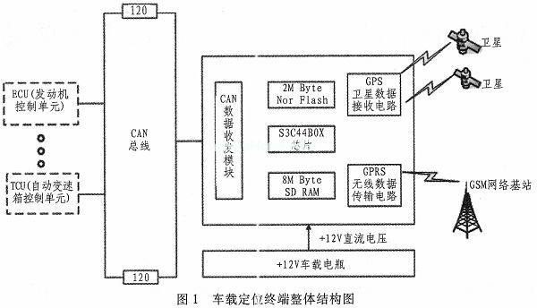
In the practical application of vehicle positioning terminal, the main factors affecting the data interaction speed depend on the processing speed of the CPU, the reading of the electronic control vehicle condition information and the real-time performance of GPS satellite data reception; the main factor affecting the stability is the hardware. Anti-electromagnetic interference performance and reasonable scheduling allocation of different priority tasks by μC/OS-II operating system. The following will elaborate and analyze several major influencing factors such as CPU circuit, GPS satellite data receiving circuit, GPRS wireless data uploading circuit and system software.
2 hardware circuit design
1) S3C44BOX processor
The S3C44BOX processor is a 16/32-bit RISC processor from Samsung that uses the ARM7TDMI core. The processor has a wealth of built-in components: 8KBcache, LED controller, SDRAM controller, 5-channel PWM customizer, PLL multiplier, IIC bus interface, IIS bus interface, 2-channel UART, 4-channel DMA and 8-channel 10-bit AD converter. These components enable the S3C44BOX processor to achieve high performance while operating at up to 66 MHz, minimizing design development costs. Compared with the traditional 8-bit single-chip microcomputer, the S3C44BOX processor can greatly improve the data processing speed of the vehicle positioning terminal.
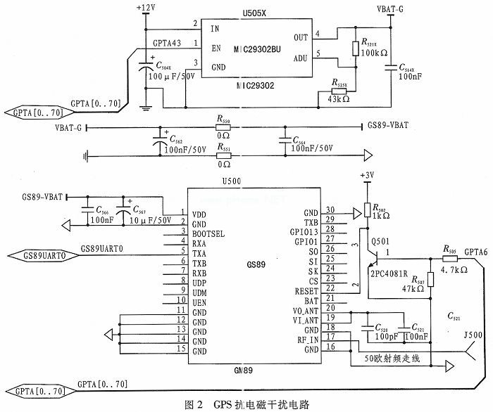
2) GPS anti-electromagnetic interference circuit
As shown in Figure 2, the core device of the GPS circuit is the GS-89M-J module. The module uses the latest MTK3329 chip as the main control chip, the positioning accuracy is less than 10 m circumference error, and the positioning time is only 1 s in the hot start mode. The MIC29302BU module is a high current and high stability voltage regulation module. It is mainly used to supply 4.2 V working voltage to the GS-89M-J module. The 5 pin in the module is an adjustable output pin. In the adjustable mode. This pin outputs a fixed 1.25 V DC voltage. In order to ensure that the module can provide a stable 4.2 V voltage, the design uses a precision resistor R521X and R525X with resistance values ​​of 43 K and 100 K to form a series voltage boost circuit. To output the 4.2 V DC voltage on the output pin of the module, the S3C44BOX controls the operation of the module by outputting a high level or a low level to the 1 pin (EN terminal - enable output, active high) of the module. Whether or not; the ground separation circuit composed of capacitor C564, polarity capacitor C562, resistor R550 and R551 is mainly used to isolate the GPS circuit from other circuits on the vehicle terminal to prevent the GPS circuit and other circuits from being coupled due to common impedance. Cross-interference; GS-89M-J reset control circuit is formed by a general-purpose I/O pin of S3C44BOX chip and transistor Q501, resistor R502, R505, R507 for ensuring the stability of the vehicle positioning terminal. In order to ensure that the master chip can reset the GS-89M-J in time when the program runs away; the impedance of the GPS antenna selected in this design is 50 ohms, because the GPS signal is a high frequency carrier signal of 1575. 42 MHz. In the transmission process, it is easy to cause signal reflection due to the mismatch between the characteristic impedance of the transmission line and the termination impedance. To prevent this phenomenon, the characteristics of the RF line used to connect the GPS antenna and the RF_IN pin of the GS-89M-J module in this design. The impedance value is 50 ohms; the GS-89M-J module receives the signals from the satellite in real time and solves them at the same time, and packs the solution results into GPGGA, GPGSA, GPGSV, GPRMC, GPVTG and GPGLL7 frame data according to the NMEA0183 protocol. S3C44BOX. The S3C44BOX receives the data frame sent by the GS-89M-J in real time through the serial port interrupt mode.
3) GPRS anti-electromagnetic interference circuit
As shown in Figure 3, the core device of the GPRS circuit is the SIM900 module. The SIM900 is designed with power-saving technology and consumes only 1.0 mA in sleep mode. At the same time, the module embeds the TCP/IP protocol, which improves the development efficiency of the user's application of the module for wireless data transmission. The NC7WZ07 in the circuit is a high-speed level conversion chip, which can convert the 4.2 V serial signal output from the SIM900 into a 3.3 V serial signal that can be received by the S3C44BOX, enabling the unobstructed communication of the SIM900 and the S3C44BOX; MOLEX- in the circuit 91228 is a SIM card holder. In order to prevent the SIM card from being interfered by electrostatic discharge and high-frequency signals, the SMF05C is used to protect the SIM card. To prevent the UHF signal from the SIM900 from being reflected to the SIM card, the signal reflection is reduced. Signal quality, here select 22 ohm resistors R614 and R613 for impedance matching; S3C44BOX can send a high level of 1 s to the SIM900 1 pin (PWRKEY pin - electrical switch pin) Control the module to be turned off and on; the S3C44BOX can reset the module by sending a high level to the SIM pin 14 pin (NRESET pin - low level reset pin); like the GPS circuit, the GPRS circuit The characteristic impedance of the RF line used to connect the GPRS antenna to the SIM900 RF_ANT pin is 50 Ω; the SIM900 receives the data packet from the S3C44B OX through the serial port and uploads the data packet to the monitoring center via the GPRS network.
It is a new type of terminal block with spring device, which has been widely used in the world's electrical and electronic engineering industry: lighting, elevator lifting control, instruments, power supply, chemistry and automobile power, etc.
Spring type terminal block
Spring type PCB terminal, the connection mode is divided into cage spring connection and butterfly spring connection, which is fast and convenient for wiring and improves the operation efficiency.
It can be used to connect all types of conductors with cross-section of 0.2mm to 16mm, with spacing of 2.5mm-15.0mm.
PCB Spring Terminal Block Section
PCB Spring Terminal Block
ShenZhen Antenk Electronics Co,Ltd , https://www.antenk.com