Abstract: This paper introduces the self-developed intelligent car airbag control system. The system is mainly composed of single-chip microcomputer, sensor, ignition circuit, etc. The ignition control algorithm is used to judge the acceleration signal of the car and output the ignition pulse. The system has the characteristics of small size, high reliability, strong anti-interference ability, self-diagnosis, etc., and has achieved good results in both the trolley test and the actual vehicle test.
Keywords: car airbag control system single chip design
This article refers to the address: http://
In China, with the popularity of automobiles, the number of traffic accidents and casualties is also increasing year by year. How to effectively protect the life of the occupants in the event of a car collision accident becomes an urgent problem to be solved. As a protective device used in conjunction with safety belts, the airbag can effectively protect the occupants. It has been popularized in Europe and the United States, and has become the main equipment for protecting occupants1. It has successfully saved many lives and shows Its practicality. As the core component of the air bag system, the control system is the core technology of each manufacturer's strict confidentiality. Therefore, the development of its own control system has become the key to developing the car airbag and solving the occupant protection problem in China.
The task of the air bag control system is to accurately determine the collision strength of the accident and to explode the air bag. The control system mainly includes mechanical, analog electronic and intelligent ones. The first and second generation of mechanical and analog control systems, due to structural limitations, have great limitations and applications are decreasing. Most systems now use the third generation of intelligent control systems with microprocessors. It uses a single-chip microcomputer to calculate the signal measured by the electronic acceleration sensor. It is considered that when a collision occurs and a certain intensity is reached, the output ignition pulse detonates the gas generator, and a large amount of gas is quickly filled to fill the air bag 3. The control algorithm of the intelligent control system is realized by software, which greatly improves the flexibility of the algorithm, and has the functions that can not be realized by the previous two generations of control systems such as recording accident information and communication with a computer.
Based on the research of foreign advanced control systems, this paper puts forward the design scheme of intelligent control system, and carries out the test of trolley and real vehicle, which proves that the control system can accurately determine the crash accident and explode the airbag.
1 Control system design
1.1 Requirements for air bag control system
Due to the special nature of the work task, the car airbag control system must meet the following requirements in addition to the ignition judgment and the ignition signal.
(1) Strong anti-interference ability
If the air bag system is accidentally exploded, it will not only cause horror to the occupants, but may even cause an accident, so it must have high anti-interference ability. If the car is disturbed by rough roads, it will produce a large deceleration. The system should be able to recognize this situation without a gas bag.
(2) High reliability and working stability
Due to the complex working environment of the car and the work requirements that do not allow ignition failure, the airbag control system must have high reliability and stability. In addition, after the collision, the power supply may be damaged first, so the system is required to continue to work for hundreds of milliseconds after power failure.
(3) Compact structure
In addition to meeting the above requirements, the entire system should also minimize the size and use fewer components to reduce the complexity of the system and improve reliability. At the same time, it can also reduce the power consumption of the system to try to maintain the work after power failure.
1.2 Control system overall plan
The control system consists of two parts: hardware and software. Figure 1 is a block diagram of the composition of the control system.
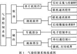
The air bag control system hardware consists of two parts, one part is the electronic control unit of the vehicle part, including the control chip, sensor, ignition circuit, indicator circuit, etc.; the other part is the ground part, including serial communication circuit and computer system, and printer Wait for the post-processing device.
Corresponding to the hardware part, the control system software is also composed of two parts, one part is the MCU part, including real-time acquisition and control software and online communication software; the other part is the microcomputer part, including online communication software and subsequent data processing software.
The working process of the airbag control system is: the system is fixed on the car. After the power is turned on, the system starts to work. After the air bag is exploded, the accident data is recorded, or the system self-test fails, the host computer (microcomputer) passes RS-232. The interface communicates with the control system to read the collision record, fault record and analyze it.
1.3 Control System Hardware
The electronic control unit is the important hardware of the entire control system, responsible for system management, power supply, acceleration measurement, air bag ignition drive, indicator display, data acquisition and other functions.
1.3.1 Overall plan
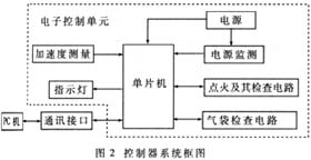
The hardware block diagram of the air bag control system is shown in Figure 2. The electronic control unit is composed of a power supply, a microprocessor, a sensor, a filter, an ignition and detection circuit, and an air bag inspection circuit. Considering the connection between the system and the outside world, there are also indicators and communication interfaces.
1.3.2 Single Chip Microcomputer
According to the requirements of the air bag control system, MOTOROLA's MC68HC11E9 MCU is selected, which has the following performance 4:
· 512 bytes of RAM: A certain number of acceleration signals can be collected in the event of a collision as a basis for determining ignition.
· 512 bytes of EEPROM: The recorded accident data can be saved for a long time in case of loss of power for accident analysis.
· 12K bytes of EPROM: The program can be solidified in the MCU without external expansion memory, which reduces the complexity of the system and improves reliability.
· A sufficient number of A/D conversion channels: A/D conversion can be directly performed on the acceleration signal and the inspection results of the air bag and the ignition circuit, thereby saving the dedicated A/D chip and improving the reliability of the system.
· With asynchronous serial communication interface, it can realize communication between system and computer.
It can be seen that the single-chip microcomputer has various performances required for the airbag control system, which can greatly save the number of special-purpose chips and reduce the complexity of the system. The clock frequency of the MCU is chosen to be 3MHz, which can fully meet the working requirements of the airbag control system.
1.3.3 Power supply
At the moment of bursting the air bag, the current of the system is quite large. If the power supply is improperly selected and the power supply is unable to provide a large instantaneous current and the ignition voltage is greatly reduced, the ignition may not be possible or the system may be stopped due to the low power supply voltage. Automotive batteries can provide short-time, high-intensity currents. Under normal circumstances, they can fully meet the ignition requirements. They can be selected as the control unit power supply and ignition power supply, and can also reduce the complexity of the system. However, the voltage fluctuation of the car battery is very large, so the power supply part needs to take corresponding measures such as filtering. In order to reduce the number of components and improve reliability, the selected components are required to operate at +5V.
In order to ensure that the system can still work normally for hundreds of milliseconds and the air bag can be reliably located in the case of power loss, a large capacitor is designed in the power supply section.
In order to prevent the system from malfunctioning when the voltage is too low, a power supply monitoring circuit is also designed to realize the function of low voltage prohibition.
1.3.4 Acceleration measurement circuit
The system uses a special capacitive silicon micro-acceleration sensor for the air bag system produced by MOTOROLA. Compared with the traditional piezoresistive sensor, it has the following advantages:
1 to achieve full circuit diagnostics, improve system reliability.
2. The integration is improved, and A/D conversion can be performed without using an amplifier circuit.
In order to eliminate the interference of high frequency noise, the acceleration signal is generally filtered in the control system. The characteristics of the filter and the filter frequency have a great influence on the ignition control. With reference to the car crash test method, the filter frequency of this circuit is selected to be 100 Hz. The filter uses the MAX291 filter circuit MAX291. It is an 8th-order Butterworth low-pass switched-capacitor filter chip that can be powered from a single supply +5V. The switched capacitor filter is an integrated device with reliable performance and compact structure to better meet the requirements of the control system. After the filtered acceleration signal, it can enter the MCU for A/D conversion.
1.3.5 Ignition circuit and air bag detection circuit
The point-explosion condition of the gas generator is a current pulse of 2A, 2ms. Obviously, if you use the output port of the MCU directly, although it can provide enough voltage, but can not provide such a large current, it is necessary to design an ignition circuit to accomplish this task. The ignition circuit acts as a switch, and is normally in a normally open state. When the ignition is started, the ignition signal from the single chip microcomputer controls the switch to close, and the ignition voltage is applied to both ends of the gas generator bridge wire for a certain period of time. For reliable ignition, the ignition voltage should be greater than 4V, where the power supply of the electronic control unit (ie the vehicle battery) is used as the power supply 2 for the ignition circuit. Figure 3 is a schematic illustration of an ignition circuit.
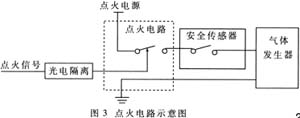
In the driving circuit, the isolation between the control circuit and the main circuit is realized by photoelectric coupling to ensure the safety of the circuit and improve the anti-interference ability. In order to prevent mis-ignition, a mechanical safety sensor is connected in series between the ignition circuit and the air bag. It is in principle a mechanical accelerometer that is normally open in normal condition. When the deceleration reaches a certain intensity, the sensor closes and allows the ignition current to pass. The general road surface interference is not enough to make it closed. At this time, even if there is a wrong ignition signal, the air bag cannot be exploded.
In order to improve the reliability of the system, the ignition circuit is designed with self-checking capability and the ability to detect the condition of the air bag. When it is found that the air bag cannot be reliably exploded, the system drive indicator light displays the fault information and informs the driver to repair in time. When detecting the air bag, it can distinguish between normal, short circuit, open circuit and poor contact.
1.4 Control System Software
1.4.1 Microcontroller Software
The software of the single-chip microcomputer has two purposes. On the one hand, it is used to realize the real-time vehicle data acquisition and the ignition control of the airbag in the collision of the vehicle; on the other hand, it realizes the communication between the vehicle data acquisition system and the microcomputer.
The system main program includes system initialization, system self-test, fault code setting, and indicator driver. The process is shown in Figure 4.
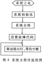
The system self-test part includes self-test of EEPROM, acceleration sensor, ignition circuit and air bag. After the self-test ends, save the result, set the fault code and turn on the interrupt, that is, enter the normal working state, cycle the drive indicator to display the system status, and wait for the interrupt to occur.
The data acquisition and control program is mainly responsible for real-time data acquisition, using the ignition algorithm to calculate and judge the data collected, and issue an ignition signal. After the ignition, the status code is also set to save the data. In order to comprehensively analyze different accident situations, the waveforms of the accidents that are not enough to be ignited but still have a certain strength should be recorded, so that the system has the function of "black box". The process is shown in Figure 5.
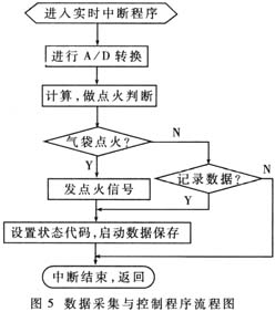
The program uses real-time interrupts and is executed every 1ms.
The online communication program completes the communication with the microcomputer, and completes the accident data uploading, system state uploading, and clearing the data saved in the EEPROM according to the instructions of the microcomputer. The program is handled in an interrupt mode.
1.4.2 Microcomputer Software
The microcomputer software includes communication program and post-processing. The microcomputer instructs the MCU to upload accident data and system status through the communication program, and analyzes and processes the result.
2 test
The automobile crash test is an effective means to test the working condition of the air bag system, which is divided into a trolley simulation test and a real vehicle test.
2.1 Trolley test
The test was carried out by the trolley hitting the hydraulic buffer to simulate the collision waveform of the car, and it was carried out on the test trolley of the T-Sports Laboratory of Tsinghua University. In order to save, the ignition tube is used instead of the air bag to observe the operation of the control system. The test speed is increased from 10km/h to 48km/h. When the vehicle speed is lower than 20km/h, it should not be ignited. When it is higher than 30km/h, it should be ignited 1. Table 1 shows the operation of the controller during the test.
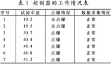
Finally, install the air bag for the trolley test. The results show that the control system is accurately ignited when the vehicle speed is higher than 30km/h, less than 20km/h, and the data can be reliably recorded.
2.2 Real vehicle test
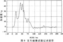
The actual vehicle test using a certain type of domestic car as the control system, the measured collision speed is 49.2km / h. The control system exploded the air bag at the exact location and recorded the data. Figure 6 shows the collision waveform recorded by this test control system.
This paper introduces the design of the intelligent air bag control system, which realizes all the functions of the air bag control system, including air bag explosion, fault diagnosis indication, data acquisition, online communication and so on. The control system has passed national acceptance and is preparing for mass production. It has the following characteristics:
1 The self-diagnosis of the circuit is realized, including memory self-test, sensor self-diagnosis, ignition circuit self-diagnosis and air bag self-diagnosis, etc., and can be notified to the user through two ways: indicator light display and online communication.
2. Designed an ignition circuit using photoelectric isolation and mechanical safety sensors, which is reliable, strong in anti-interference ability, and has the function of diagnosing air bags and ignition circuits.
3 î—¥ î—¥ combined with the hardware design of the system software, completed the functions of self-diagnosis, data acquisition, communication, and achieved ignition control. The control software makes full use of the software interrupt function of the single-chip microcomputer, and the function switching of the system does not require an external switch.
4î—¥ Compact structure, small size and low power consumption.
5. Designed the software of the microcomputer, which can deeply process and study the collision data, laying a foundation for the further development of the control system.
references
1 piece of gold for change. Research on car airbag system. Journal of Tsinghua University, 1997 11
î—¥
2 Yin Wuliang. Development and research of automotive airbag control system  PhD thesis . Beijing: Department of Automotive Engineering, Tsinghua University, 1999
3 Wang Jianqun. Development of automotive airbag system and vehicle data acquisition system  PhD thesis . Beijing: Department of Automotive Engineering, Tsinghua University, 1995
4 MC68HC711E9 Technical Data. MOTOROLA
1.25mm Wire To Board Connectors are avialable in different terminations and sizes intended for use on a variety of applications. These connectors provide power and signal with different body styles, termination options, and centerlines. To find the wire to board set required, click on the appropriate sub section below.
Description
1.25mm wire-to-board connector system is designed for a wide variety of applications in Industrial, Automotive, and Consumer markets.
The comprehensive range consists of terminals, crimp housings and PCB headers in straight and right angle, surface mount and through-hole configurations. It is available in 2 to 15 circuits in a single row. 1.25mm wire-to-board solution conforms to the EU Industry Safety Standard. Pcb Header material meets halogen-free requirements and can be operated in the temperature range from -40°C to +105°C.
Saves space with a 1.25mm pitch
Suitable for Industrial, Automotive, and Consumer markets
Crimp housing with friction feature
Conforms to EU Industry Safety Standard
Accommodates wire range up to 32AWG-28AWG
Features
Three plating versions - Tin 15μin Gold, 30μin Gold and Gold Flash
Fully polarized housings
Crimp housing with friction feature
Tape and Reel packaging with pick up cap
UL94V-0 flammability rated LCP material
Halogen-free resin material
RoHS compliant and lead-free
Benefits
Supports applications in a wide range of environments
Prevents accidental mismating
Provides additional retention and prevents harness-to-header mismating
Pick and place for SMT production process
High flammability rating
Meets environmental requirement
Meets environmental, health and safety requirement
Applications
Consumers
Car Audio
Industrial & Instrumentation
Industry Control
Instrumentation/Metering
Office Equipment
Small Motor/Robot Control
Security
Alarm Systems
Vending POS Machine
1.25Mm Wire To Board Connectors
Automotive Connector,1.25Mm Wire To Board Connectors,1.25Mm Pcb Wire To Board Connector,1.25Mm Pin Wire To Board Connector,.049" Pitch Wire To Board Connectors
ShenZhen Antenk Electronics Co,Ltd , https://www.antenk.com