0 Introduction The car has a stable power supply system during driving, which is the most basic guarantee for the normal operation of various electronic devices. In the event of a power failure, in order to troubleshoot, we need to know in real time the status of the power supply when it fails. This requires us to capture real-time fault data from the power supply at the moment of power failure and to preserve it in a stable environment. Real-time collection and recording of system power parameters can better understand the actual working conditions of the system power supply, so that more accurate experimental data can be obtained in the test and stereotype test. The purpose of the power supply monitoring system is. Real-time measurement and recording of the current and voltage of the system. After recycling, connect to the PC through serial port or USB, and transmit the collected data to the PC for analysis and processing in time. This equipment is used in the black box on the aircraft and the ship. "There are similar places. Tested by special vehicles, the system has the characteristics of anti-overload shock, anti-interference, data loss without loss, good three-proof performance, external real-time clock chip, minimum sampling period of 0.1 ms, which can effectively capture voltage jump. Change the moment, and record the fault data in real time to meet the actual requirements. This article introduces the example of connecting the power monitoring system to the PC using the serial port.
This article refers to the address: http://
1 Hardware circuit design of power monitoring system The voltage sampling accuracy of the power monitoring system is 0.1%, and the current sampling accuracy is 1%. Among them, the voltage is two, and the current is two. For this purpose, the hybrid MCU C8051F040 is used, and the 12-bit ADC is used. The maximum sampling rate is 200 kHz. Secondly, the power monitoring system does not need to lose access speed and power loss. The existing FLASH is difficult to meet the requirements. For this purpose, ferroelectric memory (FRAM), a new type of power-down non-volatile memory introduced by Ramtron in recent years, combines high performance and low power operation to save data without power. FRAM overcomes the shortcomings of E2PROM and FLASH writing time and low erasing times, and increases the reliability of data compared to the lithium battery + SRAM scheme. The storage capacity of FM20L08 is 128 k×8 b. Its main features are as follows: 3.0 V to 3.65 V single power supply; parallel interface; available in SOIC and DIP packages; low power consumption, quiescent current less than 15, read The write current is less than 10 mA; the data can be stored for 10 years after power-off; the reading and writing is unlimited.
2 The working principle of the power monitoring system and the hardware connection system are successfully reset, start data acquisition, and the collected data is compared with the voltage required by the system. If it meets the range of system voltage requirements, it will be discarded; otherwise it will be stored in FRAM memory. . After the data storage is full, stop the acquisition and alarm. The system principle is shown in Figure 1.

The system voltage is sampled by a proportional resistor plus a reverse diode with a sampling range of 9 V to 36 V. The current is sampled using a multi-pole current sensor LTS25-NP with a sampling range of 16 A to 20 A DC. The sampling method connects the multi-pole current sensor in series with the circuit. Since the resistance of the multi-pole current sensor is very small, it is 0.18 mΩ, and there is no voltage drop, which meets the requirements of the design specification.
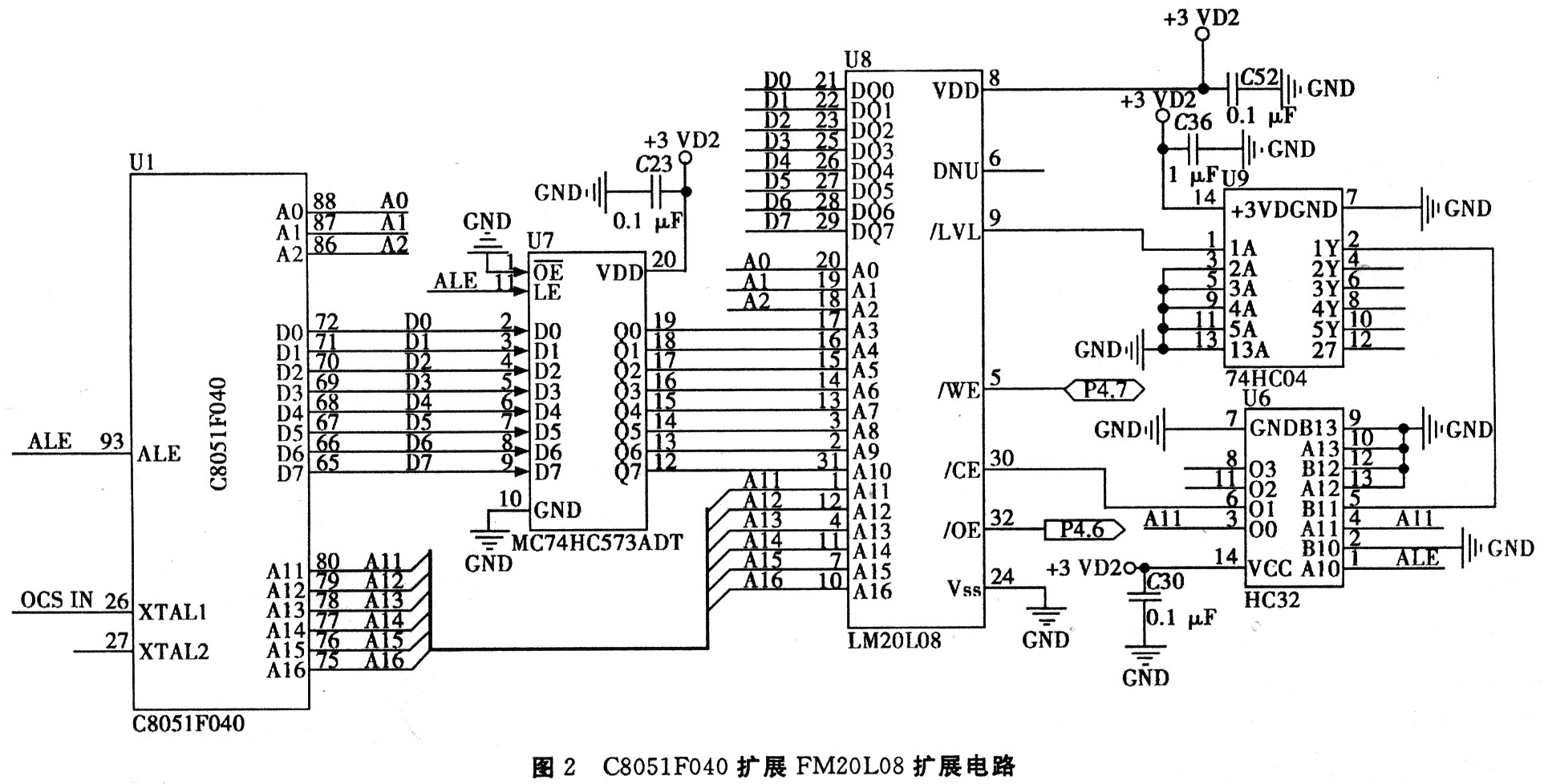
The expansion of the serial port by the MCU has a very mature example. This article is not listed here. Only the schematic diagram of the FRAM controlled by the MCU is listed below. In this system, the address signal multiplexing mode is adopted, so that an ALE signal can be generated. The FM20LO8 itself has a latch and the chip select signal CE cannot be grounded directly like the SRAM. A precharge time is required. This signal is generated by HC04 and HC32. Moreover, the address signal needs to be latched on its falling edge, as shown in Figure 2.
3 software design
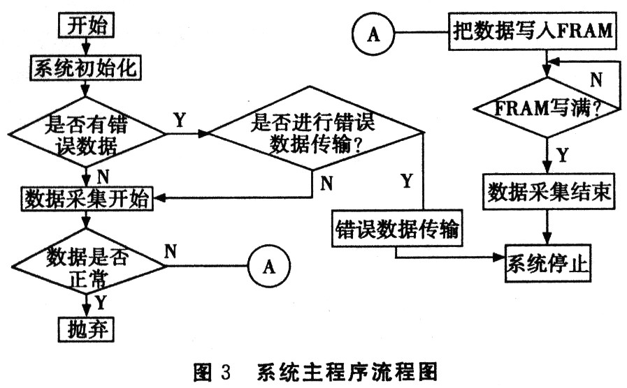
3.1 Software design of power monitoring system The power monitoring system software is divided into main program, data acquisition program and serial communication program. The working process is as follows: the power monitoring system is first powered on. After resetting, the MCU enters the subroutine of data acquisition and loops. When the FRAM is full, the acquisition is stopped, and the alarm is entered into the main loop phase. Wait for the serial signal to be externally triggered to enter the data transfer subroutine. If the error data transmission is not performed at this time, after the next reset, the wait state is entered and data acquisition is not performed until the data acquisition command is received. If the serial port signal has an external trigger, the error data is sent to the PC through the serial port. The program flow is shown in Figure 3.
3.2 Host computer program design of power supply monitoring system Establishing stable, reliable, convenient and fast data communication is a necessary condition for the system to finally realize its function. Under Windows XP, using VC++6.0 communication control MSCOMM to design the software, realize the data exchange between PC and MCU, only need to set the port simply. In the Windows environment, the serial port is part of the system resources. The application requests the resource request (opens the serial port), and the resource must be released (the serial port is closed) after the communication is completed.
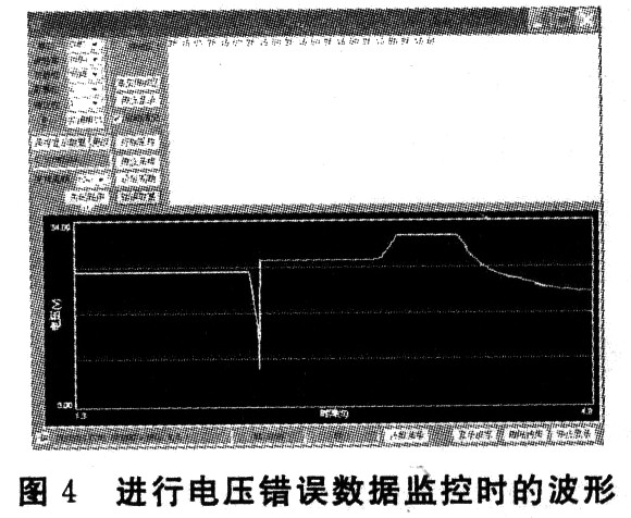
4 Conclusion This recorder has its own characteristics, with the advantages of fast acquisition speed, anti-overload, good three-proof performance, etc. It has been proved by vehicle simulation test that it can meet the test requirements, can effectively capture the voltage jump instant, and can record in real time. The fault data solves the existing test problems and meets the requirements of the design specification. The waveform display results when voltage error data monitoring is performed are shown in Fig. 4.
Block NdFeB,Permanent Block NdFeB,Strong Block NdFeB
Ningbo Wewinmagnet Co.,Ltd , http://www.wewinmagnet.com