1 Introduction
The CAN bus is a serial communication network that effectively supports distributed control or real-time control. Its application range from high-speed networks to low-cost multi-line networks. The CAN bus has the following features:
(1) CAN is the only international standard field bus to date.
(2) CAN works in multi-master mode, and any node on the network can actively send information to other nodes on the network at any time, regardless of master-slave.
(3) On the message identifier, the nodes on the CAN are divided into different priorities to meet different real-time requirements. The data with higher priority can be transmitted within 134 us.
(4) CAN uses non-destructive bus arbitration technology.
(5) CAN nodes can realize point-to-point transmission by means of identifier filtering of messages, and transmit data in several ways, such as point-to-multipoint and global broadcast, without special "scheduling".
(6) The direct communication distance of CAN is up to 10 K meters; the communication rate is up to 1 Mbps.
(7) The number of nodes on the CAN mainly depends on the bus driver circuit, and currently there are more than 110.
(8) The message adopts a short frame structure, the transmission time is short, and the probability of interference is low, so that the error rate of data is lowered.
(9) Each frame of CAN has CRC check and other error detection measures, which has excellent error detection effect.
(10) The CAN communication medium can be a twisted pair cable, a coaxial cable, or an optical fiber.
(11) The CAN node has an automatic shutdown output function in severe cases, so that the operation of other nodes on the bus is not affected.
This article refers to the address: http://
(12) CAN bus has a high performance price ratio.
2. Topology of the body network For the electric vehicle body network [5], there are many electronic devices and the position distribution is disorderly. In order to facilitate the management of the entire network, the entire body network can be divided into different nodes according to the different topology. The division of network nodes is based on the principle of partitioning. The electronic devices in the nodes can communicate with each other through the network, and the electronic devices in different regions communicate through different network nodes. Based on the analysis of the equipment of the electric vehicle body, the vehicle body network is divided into an instrument panel node, a left front node, a right front node, a left rear node, and a right rear node.
For the body network, the electronic equipment does not have high requirements for communication speed. Therefore, according to the definition of the SAE body network of the American Society of Engineers, the class B bus is selected and the transmission rate is 10-125 kbps. The topology of the network is shown in Figure 1. Show: 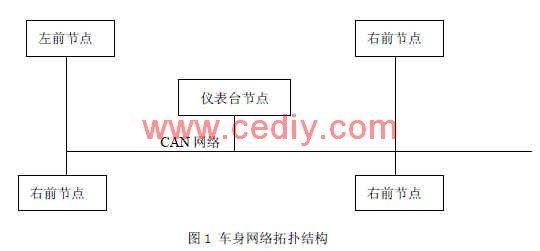
3. The communication protocol message design adopts the general message form of CAN bus [6] The maximum data length per frame is 8 bytes.
The main task of the communication protocol message is to send the message and receive the message, and the message is received and sent in the format of the data frame [7]. The data field of the data frame can send or receive 8 bytes of message content. Each byte has 8 bits and can only send or receive 1 bit at a time. The format of the communication protocol packet is shown in Table 1. 
4, based on the LABVIEW protocol implementation hardware using MC9S12DP51216 microcontroller [7]. The MC9S12DP51216 microcontroller bus uses twisted pair and desktop host computers.
4.1 Defining Data Structures In LABVIEW, the Virtual CAN Interface (VCI) library is an application interface specifically designed for use with ZLGCAN devices on a PC. These library functions can be used directly from LABVIEW. First create a VCI function library data structure, define the data type as a cluster, and call the library function [8] at the same time.
The program of this system realizes the transmission and acceptance of data, and displays the data sent and received on the front panel through the CAN bus. The program contains three main While loops: the main loop, the send data loop, and the receive data loop. These three loops run in parallel and are independent of each other. The main loop handles the interface that interacts with the user, which uses an event-driven mechanism to handle the user's operations on the front panel and communicates with the data loop and the receive data cycle through user events. It includes the following functions: turning the device on/off, timeout, starting CAN, resetting CAN, reading device information, reading CAN status, reading error messages, and clearing buffers.
4.2 Implementation of the data transmission and reception function Accept and send data through the buttons on the control panel, call the VCI function, and display the data in real time. The block diagram is shown in Figure 2 and Figure 3.

4.3 Drive Module Design
The driver module includes the timeout module, stop module, OpenDevice module design, StartCAN module design, ResetCAN module design, Clear Buffer module design, GetBoradInfo module design, GetErrorInfo module design, GetStatus module design and TREvent module design. . Each module implements the required functions by designing control keys in the control panel and calling sub-functions.
The block diagram of the TREvent module is shown in Figure 4. This module is mainly used to display the data sent and received. 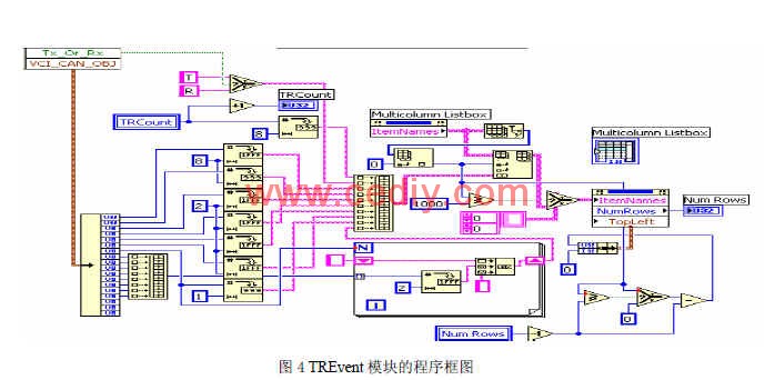
5, system testing
5.1 Establishing the Control Panel and Display Panel The body network system must correctly reflect the communication status. First, collect a large number of signals on the body CAN bus under the working condition of the car. These signals can be divided into two broad categories: open and analog signals.
The switch signal is also called digital signal, and mainly includes low beam switch, high beam switch, brake light switch, fog light switch, turn signal switch, air conditioner switch and wiper switch. There are also some indication signals that need to be transmitted through the CAN network to display the amount in the meter. These quantities include CAN fault indication, seat belt indication, high beam indication, reverse indication, left steering indication, right steering indication, rear fog light indication, brake failure alarm indication, parking indication, and the like.
There are also some analog signals in the body network, including motor speed, vehicle speed, battery power, battery voltage, battery temperature and so on.
The control panel and display panel of the switch module are built by LABVIEW software. Through the buttons on the control panel, the corresponding data can be sent and the corresponding signal displayed on the display panel. 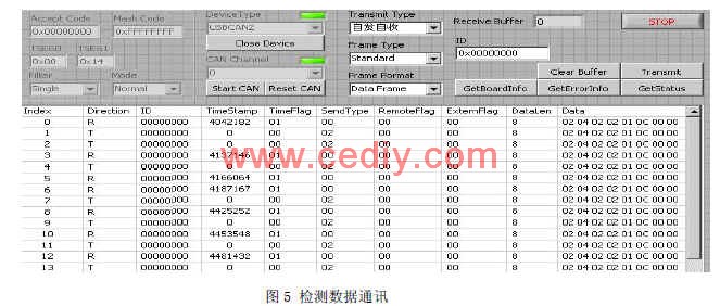
5.2 Data Reception and Transmission Detection The transmission and reception of detection data, in the LABVIEW, set the data transmission and reception behavior spontaneously [9]. Start CAN, the indicator light is on, click the send button, the data is sent out in the form of spontaneous self-receiving [10], as shown in Figure 5. 6. Conclusions This paper focuses on the characteristics of electric vehicles and establishes an electric vehicle body network. Based on the analysis of the CAN bus, the communication protocol of the application layer is established. Use LABVIEW software to write the upper machine software of CAN network communication. In order to verify the data transmission and reception of the communication, the simulation is carried out in the LABVIEW software. After testing, the system can well realize the communication requirements of the electric vehicle body network.
The author of this article is innovative:
The CAN bus technology was used to establish a pure electric vehicle body network, and the network connection was realized by LABVIEW software. And through the system communication test, the feasibility of the network is verified.
references
[1] Hu Wei, Song Hui. Electric Vehicles. People's Communications Press. Beijing. 2006.
[2] Shu Hua, Yao Guoping. Automotive Electronic Control Technology. People's Communications Press. 2008.
[3] Yan Mingkuan. CAN bus principle and application system design. Beijing Aerospace University Press. 1996.
[4] Zhou Kai, Guo Dong. Virtual Instrument Engineering Design and Development. National Defense Industry Press. August 2004.
[5] Cui Shengmin, Xiong Jie, Wang Dafang. Automotive body CAN network system design. 2009, 1:32-34.
[6] Xu Wei, a CAN bus protocol for distributed measurement systems. Microcomputer Information. 2007, 11-2: 32-34.
[7] Liu Jianfeng, Gui Weihua, Huang Zhiwu, Tong Haitao, Qi Jieren. A CAN bus scheduling algorithm applied to locomotive brakes. 2009, 1-1: 183-187.
[8] Wang Feng, Yan Xuede, Principles and Application Technology of Single Chip Microcomputer, Beijing University of Aeronautics and Astronautics Press, 2007.
[9] Cai Guoying, Zhang Hongqun. Signal Generation and Analysis System Based on LabVIEW. Foreign Electronic Measurement Technology. 2007, 7:12-14.
[10] Ma Yingjian, Cao Jie, Song Peng. Design of 3458A Data Acquisition System Based on LabVIEW. Electronic Measurement Technology. 2009, 1:131-143.
Vcb Breaker,Vcb Panel,Vcb Online Banking,Automatic Vcb
Wecome Group Imp. & Exp. Co., Ltd. , http://www.china-vacuum-interrupter.com