In recent years, ferroelectric memories composed of ferroelectric field effect transistors (FeFETs) having a metal-ferroelectric-insulator-semiconductor (MFIS) structure have become the most potential due to their non-destructive readout and high storage density. One of the next generation of non-volatile memory devices. The MFIS structure is the core component of the FeFET, and its electrical performance will affect the storage capacity and stability of the ferroelectric memory. In the existing research, the researchers used experimental methods to study the electrical properties of MFIS structural devices, and on the other hand tried to theoretically study the electrical properties of the devices.
This paper will use Silvaco's Atlas device simulation software, combined with Miller et al's iron electrode model and charge slice model, to simulate the C-V characteristics and memory window of MFIS structure devices, discuss application voltage, insulation thickness and material pair. The impact of MFIS structural devices is an effective way to improve the performance of MFIS structural devices.
1 MFIS device structureThe MFIS structure is based on a conventional MOS capacitor, and a ferroelectric material having a polarization behavior is added between the metal electrode and the insulating layer, and the polarization behavior of the ferroelectric layer is used for binary data storage. Figure 1 shows a typical MFIS structure and its equivalent circuit. The thickness of the ferroelectric layer is df and the thickness of the insulating layer is di. Ideally, the effects of trapping charge, interface state, and internal space charge and impurities in each layer are not considered. The upper electrode of the capacitor is a Schottky contact and the lower electrode is an ohmic contact. The substrate is uniformly doped with p-type silicon and the thickness is required.
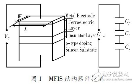
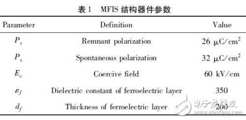
Silvaco's device simulation software, Atlas, simulates and analyzes DC, AC, and time domain responses of semiconductor devices in 2D and 3D modes. In order to consider the saturated state and the unsaturated state of the ferroelectric layer planned behavior in the MFIS structural device, the iron electrodeization model proposed by Miller et al. is improved. Introducing two polarization models Ferro and Unsat in the Model statement. Ferro, the relevant parameters of the device are set in the Material statement. Since the MFIS structure device works in a high frequency state in practical applications, it is necessary to set the Fer-roDamp parameter in the Ferro model to 1. The upper electrode and the lower electrode of the MFIS structure are set to Schottky contact and ohmic contact, respectively, in consideration of the work function relationship between the ferroelectric thin film, the semiconductor substrate, and the metal electrode. The ferroelectric layer is made of BNT ferroelectric thin film with a thickness of 200 nm. The parameters can be obtained from the literature. The specific parameters are shown in Table 1.
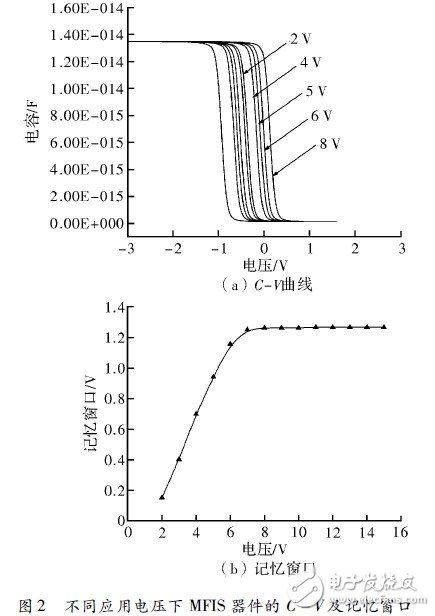
The application voltage can affect not only the storage capacity and stability of the ferroelectric memory, but also its compatibility with the semiconductor integrated circuit. The C-V characteristics and memory window of the MFIS device at different application voltages are shown in Figure 2. The insulating layer is CeO2 and the applied voltage is increased from 2V to 5V. It can be seen from the figure that due to the polarization behavior of the ferroelectric layer, the C-V curve of the MFIS device appears to shift in different scanning voltage directions, exhibiting a clockwise return line shape, and its width gradually increases with the application voltage. Widening. The memory window of the MFIS device gradually increases as the applied voltage increases and saturates at 8 V. The size of the memory window directly affects the stability of the MFIS device. Under the smaller memory window, the two logic states of “0†and “1†of the memory are easily confused, resulting in data access failure. Therefore, appropriately increasing the application voltage is beneficial to improve the storage stability of the MFIS device.
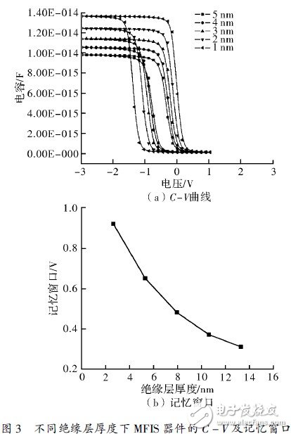
The thickness of the MFIS device insulation layer affects the performance of the MFIS structure. Figure 3 shows the C-V characteristics and memory window of the MFIS device for different insulation thicknesses. The device is applied at 5 V, the insulation is CeO2, and the thickness is increased from 1 nm to 5 nm. It can be seen from the figure that under a certain applied voltage, the C-V curve of the MFIS device narrows with the increase of the thickness of the insulating layer, and the memory window decreases accordingly. This is related to the thickness of the insulating layer reported in the literature to the electrical of the MFIS device. The impact of performance is consistent. This can be explained by the effective electric field applied to the ferroelectric layer. The effective electric field Ef on the ferroelectric layer is
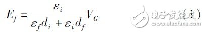
Where CG is the applied voltage; εf and εi are the relative dielectric constants of the ferroelectric layer and the insulating layer. Obviously, the effective electric field on the ferroelectric layer decreases as the thickness of the insulating layer increases, causing the ferroelectric layer to gradually move away from saturation, causing the memory window of the capacitor to decrease.
It can be seen from the formula (1) that the insulating layer having a high dielectric constant εi can increase the effective electric field distributed on the ferroelectric layer, thereby causing the ferroelectric layer to become saturated, resulting in a large memory window. In order to study the influence of different insulation materials on the performance of MFIS devices, the C-V characteristics and memory window of MFIS devices using SiO2, Si3N4, Y2O3, HfO2 and CeO2 as insulating layers were simulated and analyzed by Arias software.
Figure 4 shows the C-V characteristics and memory window of the MFIS device with different insulating layer materials at 5 V application voltage. It can be seen from the figure that the C-V curve of the MFIS device gradually widens with the increase of the dielectric constant of the insulating layer, and its memory window increases from 0.36 V to 1.09 V, and gradually becomes saturated.
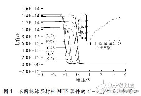
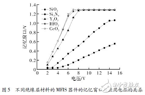
Figure 5 shows the memory window of the MFIS device as a function of applied voltage for different insulating layer materials. It can be seen from the figure that the high dielectric constant is the insulating layer jf, the memory window of the MFIS device is saturated at 7 V, and the memory window is not saturated at 15 V when the low dielectric constant is the insulating layer. This means that at a certain thickness, a high dielectric constant insulating layer can saturate the memory window of the MFIS device at a lower application voltage, thereby reducing the operating voltage, making it compatible with modern integrated circuit design processes.
Using the device simulation software Arias, combined with the ferroelectric polarization model under saturated state and unsaturated state, the effects of applied voltage, insulation thickness and material on C-V characteristics and memory window of MFIS devices were studied. The simulation results show that increasing the applied voltage, reducing the thickness of the insulating layer and using high dielectric constant materials can make the C-V curve of the device gradually widen and the memory window gradually increase. However, considering the compatibility of the MFIS device with the operating voltage of modern integrated circuits and the leakage current that may be caused by the excessively thin insulating layer, the use of a high dielectric constant insulating material as the insulating layer of the MFIS device becomes an improvement of the performance of the MFIS device. An effective way.
Portable Outdoor Power Station,Portable Solar Generator,Power Station,Power Bank Home Station
Guangdong pisen electronics co., ltd , https://www.pisenpro.com