The function of the aircraft power distribution system is to realize the transmission, distribution and protection control of aircraft electrical energy. With the rapid development of aerospace, electronics and computer technology, the number of airborne equipment has increased significantly, and the capacity of power supply systems has grown rapidly [1]. Aircraft power distribution systems are gradually moving toward automatic distribution systems based on communication buses. RS485 bus is characterized by its simple protocol and flexible configuration. It is often used as a redundancy bus for aircraft automatic power distribution systems with multiple data buses [2]. This paper mainly discusses the application of RS485 bus in aircraft power distribution system in multi-processor mode.
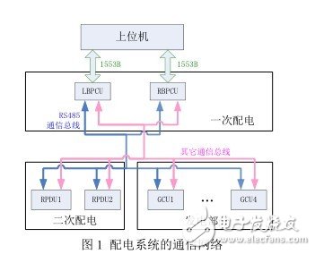
2. Structure and communication requirements of aircraft power distribution systemThe aircraft automatic power distribution system includes a primary power distribution system and a secondary power distribution system. The core control component of the primary power distribution system is a bus power controller (BPCU); the control component of the secondary power distribution system is Secondary Power Distribution Control Unit (RPDU) (RemotePower DistribuTIon Unit). The communication network of the aircraft power distribution system involved in this paper is shown in Figure 1. Among them, the BPCU communicates with the host computer through the 1553B bus, and transmits the operating status of the aircraft power distribution system to the upper computer; the BPCU and the RPDU and the generator controller GCU (GeneratorControl Unit) pass the RS485 bus and other communication buses (such as the CAN bus or 429 bus, etc.) to communicate. The BPCU monitors and manages the power distribution system based on the information fed back by the GCU and the RPDU, and realizes automatic switching of bus bar switching and high-power load to complete the distribution of aircraft power.
It can be seen from Fig. 1 that the aircraft power grid structure is complex, and there are two BPCUs working in the primary power distribution system at the same time, which are left (L) BPCU and right (R) BPCU. Therefore, the power distribution system constitutes a RS485 bus communication network with multiple processors. The functions to be implemented in the communication network are as follows: 2 BPCUs need to communicate regularly, exchange data and monitor whether the other party is running normally; 2 BPCUs need to communicate with all GCUs and RPDUs regularly to monitor the running status of the grid; GCU and RPDU under normal conditions No communication is required between them.
The RS485 bus standard is a communication standard for twisted-pair transmission lines developed by the American Electrical Industry Association. It uses balanced transmission and differential reception, allowing one transmitter on a twisted pair to drive 32 load devices [3]. RS485 communicates in half-duplex mode. When used for multi-station interconnection, it is easy to build a bus network with high reliability and wide distribution [4]. However, since the communication mode of the RS485 bus is half-duplex, that is, only one node on the bus can become the master node at the same time. If two or more nodes are in the transmitting state at the same time, the data transmission of all the senders will fail. This is the bus conflict [5]. When there are more than two nodes in the communication network, solving the bus conflict problem becomes the key and prerequisite for improving the reliability and stability of the work [6].
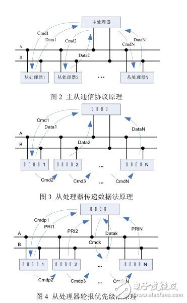
4. Bus conflict resolutionIn the communication network shown in Figure 1, there are two BPCUs communicating with multiple RPDUs and GCUs to form a RS485 communication network with multiple processors. Since the data is exchanged and transmitted in both directions, there is a bus collision problem. . The most common way to resolve bus conflicts is the master-slave communication protocol method. The principle of the master-slave protocol is shown in Figure 2. This method sets a terminal in the communication network as the master processor. The master processor sequentially issues instructions (Cmd) to the slave processors, and the slave processor sends data according to the instructions. ) sent to the main processor. The disadvantage of this method is that if the number of slave processors is large, the real-time performance of the system will decrease, and if the host processor fails, the entire communication network cannot work normally. Based on the master-slave communication protocol, the literature [7] proposes a data transfer method from the processor as shown in Fig. 3. This method saves the time for the host processor to interrogate the slave processor and improves the real-time communication. Literature [8] proposes a method for transmitting data according to the priority of the processor. The principle is shown in Figure 4. The method sends a priority reporting instruction (Cmdp) by the main processor, and the priority (PRI) is reported from the processor one by one. After scanning a round of priority, the main processor issues a finger to the highest priority slave processor (Cmdk) ) Ask for data. The priority method has a small amount of data and the real-time performance of the system is improved. However, the algorithm for calculating the priority from the processor is complicated in this method, and there is still only one main processor in the whole system, and the multi-master processing of RS485 cannot be realized. Communication.
In addition to using the master-slave communication protocol to solve the bus conflict problem, there is also a way of bus monitoring. Reference [9] introduces a method of using the hardware circuit to monitor the bus. This method realizes the multi-master communication of the RS485 bus. The disadvantage is that the additional hardware circuit will affect the RS485 bus impedance. Literature [10] proposed a method for realizing bus interception and differential delay by software to solve RS485 bus conflict. In this method, each node has different priorities due to different listening time, so it can realize RS485 bus multi-master communication very well, but due to the limitation of priority, the real-time processing of individual urgent data at some moments is better. difference.
In the RS485 communication network involved in this paper, two BPCUs simultaneously control the aircraft power distribution system to form a communication network with two main processors and multiple slave processors. The existence of two main processors makes it impossible for the entire network to rely on the master-slave protocol to avoid bus collisions; the way of listening to the bus complicates the communication algorithms of the slave processors GCU and RPDU that only need to respond. In view of the characteristics of the network containing two main processors and multiple slave processors, this paper proposes a way to solve the bus conflict by combining the principle of master-slave communication and time-series interception. The principle is as follows: according to the characteristics of the master-slave protocol suitable for the inquiry-response mode, each GCU and RPDU are used as slave processors, waiting for commands to respond; according to the time difference listening method is not limited by the number of RS485 main processors, The LBPCU and RBPCU in the communication network act as the main processor, and the time difference interception method is used to determine which BPCU occupies the bus.
This paper first improves on the basis of the priority reporting method based on the master-slave communication protocol proposed in [8]. Since the slave processor priority algorithm is complicated, in this paper, the main processor only asks whether the slave processor has data report, that is, it queries the Y/N state of the slave processor, and after the processor reports a round of Y/N state, the master The processor determines which slave processors to query for data, and regardless of which BPCU sends a Y/N status query command or a data query command, both BPCUs can receive all slave processor Y/N status or data feedback.
In view of the characteristics of two main processors in the communication network, this paper adopts the method of time difference monitoring bus to determine which BPCU is the main processor. The principle is to set different priorities for the two BPCUs, and the higher priority BPCU can seize the control of the bus. The specific method is as follows: Firstly, it is assumed that the LBPCU has the highest priority. When the data needs to be sent, the bus needs to be listened first. If the bus is found to be idle, the delay listening is started. Because the priority is the highest, the LBPCU needs to delay the listening time. RBPCU is short. If the bus is always idle after a period of time, the LBPCU can send data or instructions. After the transmission is completed, the LBPCU priority is lowered, and the RBPCU priority is increased, and the RBPCU has the highest priority.
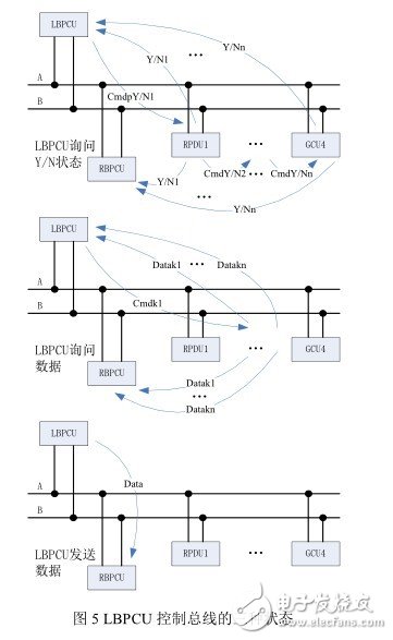
Combined with the master-slave communication principle and the differential delay listening bus method, the operation mode of the whole communication network is as follows: when the RS485 bus is idle at a certain time and the LBPCU is the highest level main processor, the LBPCU can send three kinds of data after listening to the bus: It sends the Y/N status query command cmdY/N to all GCUs and RPDUs, the second is to send data reporting instructions cmdk to some GCUs and RPDUs, and the third is to send data to RBPCU. The three sending processes are shown in Figure 5. If the LBPCU sends the Y/N status query command cmdY/N, both the RBPCU and the LBPCU can know whether all GCUs and RPDUs have data reporting requirements. If the LBPCU sends a data reporting command cmdk, the command contains all the data to be reported. From the address of the processor, these slaves perform data rounding. In this process, both LBPCU and RBPCU receive all data reports; if the LBPCU sends data to the RBPCU, the data should contain the working status of the LBPCU.
Regardless of which data is sent by the LBPCU, the priority is lowered after the action is completed, and the RBPCU raises the priority, at which time the priority of the RBPCU becomes the highest. Thereafter, when the bus is idle, the bus can be controlled by the RBPCU in the same way as the LBPCU.
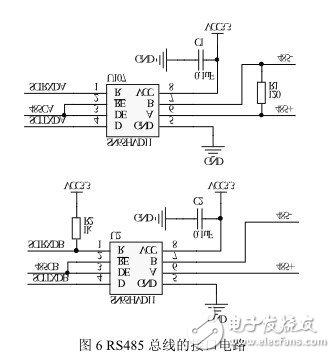
5. Multi-processor RS 4 8 5 bus implementation 5.1 RS485 bus interface circuit designIn this paper, the RS485 bus terminal consists of TI's DSPTMS320F2812 and RS485 transceiver SN65HVD11. There are two serial port modules SCIA and SCIB in the DSP. Both modules have serial port receiving pin SCIRXD and serial port sending pin SCITXD. The RS485 bus interface circuit is shown in Figure 6. The output terminals A and B of the two SN65HVD11 terminals are respectively connected to the RS485 bus A and B, thus forming the double redundancy interface of the bus terminal; the RE end and the DE end of the SN65HVD11 After parallel connection, it is connected with the control signal 485C of the main processor DSP to form a half-duplex bus interface. Therefore, the transceiver can only be in the receiving state (485C is low level) or the transmitting state (485C is high) at any time. Level); The R and D terminals of the SN65HVD11 are connected to the serial port module interfaces SCIRXD and SCITXD of the DSP respectively; R1 is 120Ω, which is the matching resistor of the RS485 bus. In the communication network shown in Figure 1, there are only 2 bus interfaces. The resistor needs to be added to meet the impedance matching requirement of the RS485 bus; R2 is the pull-up resistor of the serial port SCIB receiver. Since there is no pull-up inside the pin of the DSP, an external pull-up resistor is required to ensure that the pin is always idle when the bus is idle. High. It should be noted that in order to improve the reliability of the communication network and reduce the common mode interference on the RS485 bus, the ground lines of the nodes on the bus need to be connected to form a common low impedance signal ground.
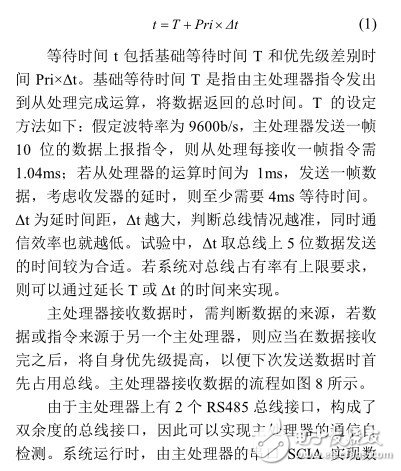
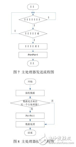
The RS485 bus communication network involved in this paper includes two main processors LBPCU and RBPCU, multiple slave processors RPDU and GCU. The software design mainly includes: the main processor sends, the main processor receives, the main processor self-detects, sends from the processor, and receives from the processor. Since the slave processor does not involve the process of priority change and bus monitoring, but only the conventional command response and data transmission, this paper only gives the flow of the main processor to send, receive and self-test. Before the main processor sends data or instructions, it needs to listen to whether the bus is idle. After completing a data or sending an instruction, the priority needs to be modified. The software flow is shown in Figure 7. In the figure, Pri represents the current priority of the main processor, and t is the waiting time. The calculation method is as shown in equation (1).
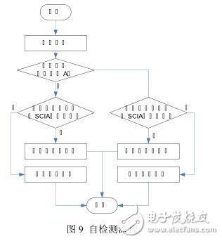
According to the sending and receiving process, the serial port SCIB monitors whether the serial port SCIA is normal or not, and realizes self-detection of communication. The process of self-test of the serial port SCIB is as follows: when the main processor sends data, the serial port SCIB reads back the data sent by the serial port SCIA. If the data is the same as the sent data, the serial port SCIA sends normally; when the main processor receives the data, If the serial port SCIB receives the same data as the serial port SCIA, the serial port SCIA reception is normal. The process of self-test is shown in Figure 9.
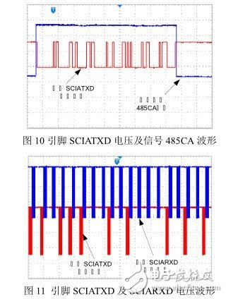
In this paper, the communication network shown in Figure 1 is constructed by using DSP and transceiver, and related experiments are carried out. Figure 10 shows the waveform of the pin SCIATXD and the control signal 485CA when the serial port SCIA of the LBPCU transmits data. It can be seen from Figure 10 that the interface circuit can work normally. Figure 11 shows the voltage waveform on the data transmission pin SCIATXD and the receiving pin SCIARXD of the serial port SCIA when the LBPCU is running. As can be seen from Figure 11, there is no bus collision when the system is running.
In this paper, a set of RS485 communication network with multi-processor is designed for the requirements of the communication network of the aircraft power distribution system and the characteristics of the RS485 bus. This paper focuses on the method of avoiding RS485 bus conflict, and proposes a method to avoid bus conflict in the communication network of aircraft power distribution system. The experimental results verify the correctness of the method. The experimental results show that the method designed in this paper can realize aircraft power distribution. System communication and avoid bus discovery conflicts. The method is equally applicable to other communication networks that contain a small number of host processors and a majority of slave processing structures.
Elux Legend 3500 Puffs,Disposable Vape 3500Puff,Elux Vape Diposable,Elux 3500Puffs Disposable Vape
Nanning Nuoxin Technology Co., LTD , https://www.nx-vapes.com