PLC ladder diagram programming is a necessary foundation for programmers
The PLC ladder diagram that we see, each program is basically composed of the series or parallel of contacts or coils, or the series and parallel of some program blocks. These series and parallel relationships constitute a certain logical relationship, so they can To achieve a specific control result, how to determine whether the contacts or blocks are connected in series or in parallel during the programming process is the key to the programming of the ladder diagram program and the core process of program writing.
Determination of the initial state of the programming element
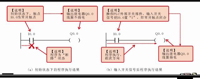
The initial state of the programming element, in simple terms, is to determine whether the contact is normally open or normally closed.
Determining the initial state of the contact depends on the control relationship of the coil when the contact is in action. Generally speaking, if the coil needs to be closed to perform the action, the initial state is the normally open contact; if it is required to open, control When the coil performs a certain action, its initial state should be a normally closed contact.
For example, when the contact I0.0 needs to be closed during programming, the coil Q0.0 is energized. It can be seen that while maintaining the initial state, the program written should be in the state of open circuit. According to the analysis, the initial state of the input relay contact should be a normally open contact. The program is written as shown in the following figure. When the external conditions are operated to close I0.0, the coil Q0.0 can be turned on.
Determination of the serial relationship between programming elements or program blocks
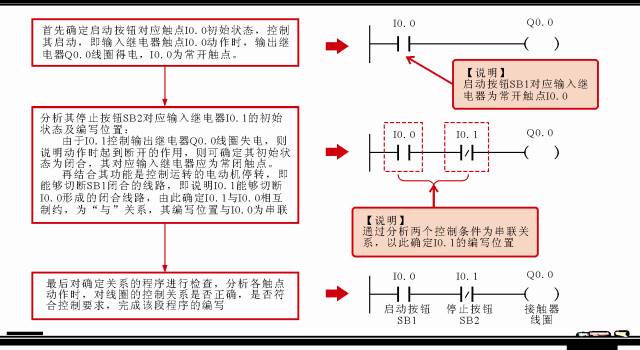
When the PLC ladder program is written, the contact that controls the same output relay coil is generally called the condition for controlling this coil. When these control conditions have a certain restriction relationship, the control of the coil can be completed, which constitutes the "and "In a logical relationship, these contacts form a series relationship.
For example, the start button SB1 is required to control the motor M to start, the stop button SB2 controls the motor M to stop, and the start and stop of the motor M is controlled by the contactor KM1, and a ladder diagram of the control process is written.
According to the control requirements, there are two control conditions SB1 and SB2 in the program, and they are input relays, and the addresses are assigned to I0.0 and I0.1. PLC external contactor KM1 is the actuator, which is assigned as the output relay. The address is Q0.0, and its programming process is shown in the figure below.
Determination of the parallel relationship between programming elements or program blocks
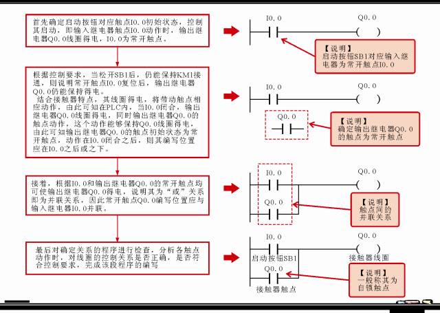
When the PLC ladder program is written, the contact that controls the same output relay coil is called the condition for controlling this coil. When any of these control conditions can complete the control of the coil, it forms an "OR" logic relationship. At this time, these contacts form a parallel relationship.
For example, it is required to press the start button SB1 to control the contactor KM1 to be energized, and the motor M is started. After the button SB1 is released, the self-locking contact of the contactor KM keeps the control signal on and the motor is still running.
According to the control requirements, there are 1 control condition SB1 in the program, and it is an input relay, which is assigned an address of I0.0, PLC external contactor KM1 is an actuator, and its coil is used as an output relay, and the assigned address is Q0.0 , Its self-locking contact is also used as a control condition, but the same component, its programming element name is still Q0.0, the writing process is shown in the figure below.
Some programming examples of PLC ladder diagram
1. PLC ladder diagram programming case of motor start and stop control
Case description:
Press the start button SB1 to control the AC contactor KM1 to be energized, and the motor M1 starts to run;
Press the start button SB3 to control the AC contactor KM2 to be energized, and the motor M2 starts to run sequentially after M1;
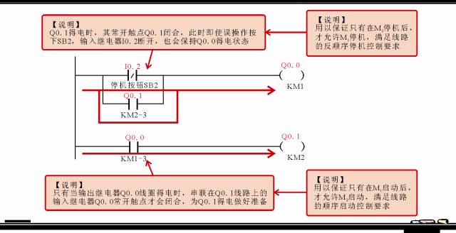
Press the stop button SB4 to control the AC contactor KM2 to lose power and the motor M2 to stop;
Press the stop button SB2 to control the AC contactor KM1 to lose power, and the motor M1 will stop in reverse order after M2.
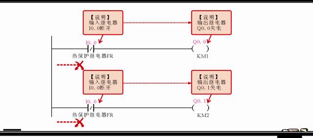
If an overload or overheat fault occurs in the circuit, the control circuit will be automatically cut off by the overheat protection relay FR.
In order to ensure the sequence in which M2 can only be started after M1 is started, the normally open contact of motor M1 AC contactor KM1 is serially connected in the M2 start control circuit.
At the same time, in order to prevent the erroneous operation when the motor M2 is started, the stop button SB2 of the motor M1 is pressed, and the motor M1 is turned off. Interlocking control.
According to the description of the control process in the programming case, we can divide the entire control relationship into 6 parts, as shown in the figure below.

Next, I / O allocation is required.

After the I / O distribution is completed, the PLC ladder diagram programming can be completed according to the control process.
1) Ladder diagram of motor M1 start control process
2) Ladder diagram of motor M2 start control process
3) Ladder diagram of motor M2 shutdown control process
4) Ladder diagram of motor M1 shutdown control process

5) Ladder diagram of motor M1 and M2 interlocking and interlocking control process
6) Ladder diagram of motor overheat protection control process
7) Merger and adjustment of procedures
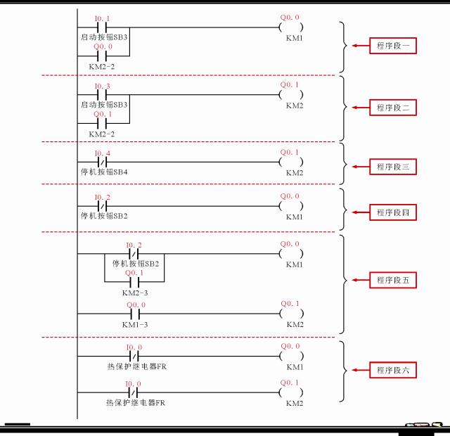
The PLC ladder program finally obtained is shown in the following figure.

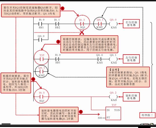
2. PLC ladder diagram programming case of automatic shuttle control of transport vehicle
Case description:
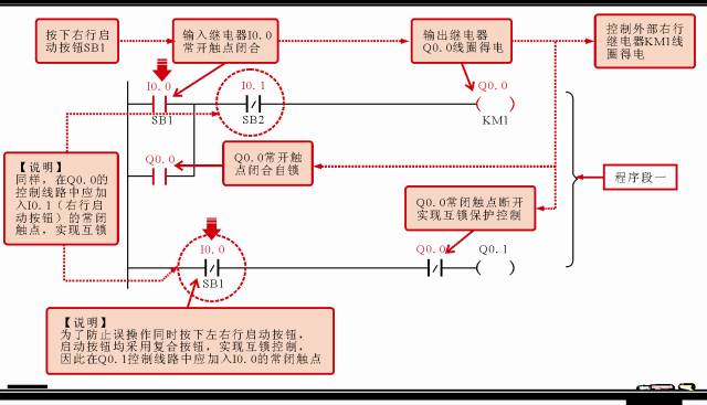
The start of the transport vehicle is controlled by the left start button and the right start button SB1, SB2;
After the transport vehicle starts running, first travel right to the limit switch SQ1. At this time, the transport vehicle stops loading. After 30 seconds of loading, the transport vehicle starts to travel left;
When the transport vehicle travels left to the limit switch SQ2, the transport vehicle stops discharging. After 60 s, the discharge ends, and then travels to the right, travels to the limit switch SQ1 and stops loading, so the cycle works.
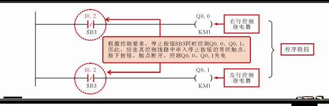
After pressing the stop button SB3, the transport truck stops working.
According to the control requirements of the automatic round-trip operation of the transport vehicle, we can divide the functional module into 4 parts, as shown in the figure below.

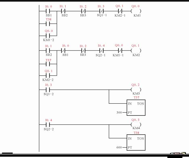
Fill in the I / O allocation table of the PLC ladder diagram before writing the program.
| Input signal and address number | Output signal and address number | ||||
| name | Code | Input point address number | name | Code | Output point address number |
| Right start control button | SB1 | I0.0 | Right row control relay | KM1 | Q0.0 |
| Left row control start button | SB2 | I0.1 | Left row control relay | KM2 | Q0.1 |
| stop button | SB3 | I0.2 | Charge control relay | KM3 | Q0.2 |
| Right limit switch | SQ1 | I0.3 | Discharge control relay | KM4 | Q0.3 |
| Left line limit switch | SQ2 | I0.4 |

After the I / O distribution is completed, the programming of the PLC ladder diagram can be completed according to the control process.
1) PLC ladder diagram of the starting control process on the right of the transport vehicle
2) Siemens PLC ladder diagram of 30s loading and automatic left-row control process
3) Siemens PLC ladder diagram for 60s unloading and automatic return (right row) control process

4) PLC ladder diagram of the control process of transport vehicle stop
5) Merger and adjustment of procedures

The PLC ladder program finally obtained is shown in the following figure.
A lot of text analysis is omitted in the two cases. If you have any questions, please leave a message to discuss.
EDP is gradually replacing the existing low voltage differential signal (LVDS) transmission interface, especially in FHD(1,920x1,080 or 1,920x1,200) or panel (UHD) that exceeds FHD resolution.
EDP can dynamically control the refresh frequency of the display panel, which is designed to reduce power consumption when displaying a still picture. In still images, the panel refresh rate can be reduced from a normal 60 images per second to any frequency that does not produce abnormal or flickering images. Reducing the refresh rate reduces power consumption and extends battery life, with some panels down to 40fps or less.
Another application that USES different display refresh rates is when playing movies or games. In game mode, the screen is often calculated by the graphics computing engine before being displayed, and there will be a delay time in the middle. In this case, the refresh frequency of the panel can be dynamically adjusted to make the screen display smooth, without distortion and delay. When playing the movie, the 24FPS picture can be adjusted to 48FPS, so as to eliminate the situation that the picture is not smooth due to the 3:2 pull-down in the traditional 60FPS mode.
Through AUX channel, eDP can control the following functions of the display panel:
Turn on or off the backlight
Backlight brightness adjustment and backlight PWM frequency are adopted.
Turn on or off dynamic backlight adjustment.
Color engine, jitter algorithm or insert black screen for adjustment.
Edp To Dp Cable,Aclu2 Edp Cable,Cg511 Edp Cable,Edp To Displayport Adapter
TONYA DISPLAY LIMITED , https://www.tydisplay.com