Abstract In order to improve the life and endurance of electric vehicle lead-acid batteries and realize efficient and fast charging of batteries, an intelligent charging system was designed. The hardware uses DC/DC forward conversion circuit to realize power conversion. At the same time, the single chip is used as the intelligent control core, and the DS18B20 is used to collect the battery temperature. According to the fast charging principle of the battery, a new charging control strategy combining phased constant current and positive and negative pulses is proposed. The modular design method is used to complete the design of each functional module, and the digital PI algorithm is used to achieve a constant phase current. The experiment proves that the intelligent charging system adopting the new control strategy charges the battery, which reduces the charging time and improves the charging efficiency.
Key words intelligent charging; forward transform; control strategy; module design
With the continuous consumption of petroleum energy, electric vehicles have been researched and promoted by countries around the world for their energy-saving and environmental protection characteristics. However, power batteries have always been the biggest bottleneck restricting the development of electric vehicles. The valve-controlled maintenance-free lead-acid battery (VRLA) has become the main power equipment for electric vehicles due to its low manufacturing cost, large capacity and stable voltage. However, if the battery is used improperly, its life will be greatly shortened. It has been found that the charging process has the greatest impact on battery life and the impact of the discharge process is relatively small. Therefore, the charging system has a decisive influence on the life of the battery.
The traditional charging method is to achieve rapid charging by increasing the charging current. However, large current charging will inevitably lead to over-current, over-temperature, polarization of the plates, etc., which seriously affects battery life. If the charge is slow with a small current, although the impact on the battery life is small, the charging time will be relatively extended. In order to solve the contradiction between charging time and battery life, through the understanding of the internal chemical characteristics of the battery charging process, a new charging control strategy is proposed to achieve efficient, fast and non-damaging charging of the battery.
1 charging control strategy
1.1 Theoretical basis of fast charging technology In the 1960s, American scientist Mamas proposed the maximum charging current and acceptable charging current curve that the battery can accept with the lowest gassing rate. The equation is ![]()
Where i is the acceptable charging current of the battery at any time t; I0 ​​is the maximum acceptable charging current; a is the decay rate constant, also known as the charge acceptable ratio.
In 1972, Mas put forward the famous Mas 3 Law at the 2nd Electric Vehicle Conference, which laid the foundation for fast charging.
The first law: a battery is discharged at any given current, and its charge acceptance rate a is inversely proportional to the square root of the discharge capacity C, ie ![]()
Where K is the discharge current constant; C is the capacity of the battery discharge.
Second law: For any given depth of discharge, the charge acceptance rate a of a battery is linear with the logarithm of the discharge current Id. Ie a=K2lgkId (3)
In the formula, K2 is a discharge amount constant, depending on the depth of discharge; k is a discharge constant.
The third law: a battery discharges through several discharge rates, and its charge acceptance current is the sum of the received currents at each discharge rate. That is, It=I1+I2+I3+... (4)
In the formula, I1, I2, I3, ... are charging currents at respective discharge rates.
Mas's law shows that during the charging process, when the charging current is close to the acceptable charging current curve of the battery, the charging is stopped at a proper time, and the discharge pulse is added during the stopping process, which can eliminate the polarization phenomenon and improve the charging acceptance of the battery. Thereby, the charging speed is greatly increased, and the capacity and life of the battery are not affected.
1.2 Charging control strategy According to the theoretical basis of Mas's law, the experiment is based on 12 V/12 AH lead-acid battery. The charging control strategy is designed to divide the charging process into three phases: high current constant current, positive and negative. Pulse fast charging, constant voltage to make up the charge, as shown in Figure 1. The rated voltage of the battery is 12 V. When the battery is fully charged, the terminal voltage is about 14.7 V. When the battery is discharged, the terminal voltage is about 10.8 V. If the battery temperature reaches 45 ° C during charging and discharging, the battery polarization is serious. The active material of the plate begins to fall off.
This article refers to the address: http://
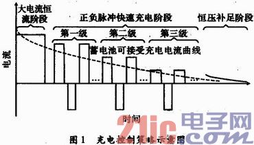
The specific control strategies for the three stages of the charging process are as follows:
(1) High current constant current phase. At the initial stage of charging, when the battery terminal voltage is less than 12 V, it means that the battery is low, and it can be charged with a large current for constant current charging, so that the battery can be charged with more power in a shorter period of time. When the terminal voltage of the battery rises to 14.7 V, the water begins to decompose, causing polarization and gassing, and charging stops at this time. After a while, move on to the next stage.
(2) Positive and negative pulse fast charging phase. During the pause phase of the pulse, as the charging current disappears, the polarization phenomenon partially disappears. Then discharge again, so that the battery reverses through a large current, which can eliminate the gas generated by the gassing phenomenon, and further eliminate the polarization phenomenon, so that the battery can receive the power faster. This stage is further subdivided into three levels, so that the charging current is close to the acceptable charging current of the battery, so that the battery will not be damaged while charging quickly.
(3) Constant pressure to complement the charging phase. After the first two stages, there is no guarantee that the battery is fully charged. At this time, it should also be charged with constant voltage. At this stage, the charging current is gradually reduced, and when it is detected that the current drops to a certain threshold, the charging is stopped. This also marks the end of the charging process.
2 hardware circuit design
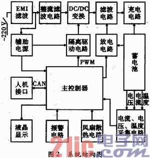
2.1 System Structure The system structure is shown in Figure 2. It consists mainly of a power conversion circuit and an intelligent control circuit. The function of power conversion is to supply the required voltage and current to the battery; the function of the intelligent control circuit is to detect the current, voltage, temperature and other parameters of the battery, and realize the intelligent charging of the battery according to the proposed charging control strategy through digital PI closed-loop regulation. .
2.2 Power conversion circuit
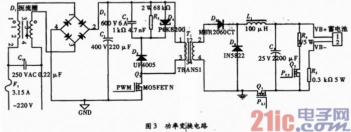
Since the system circuit power is about 150W, a low-cost single-ended forward DC/DC converter circuit is used, as shown in FIG. Firstly, the 220V, 50Hz power frequency AC mains is connected to the EMI filter. After rectification and filtering, it is connected to the DC/DC single-ended forward conversion circuit, and then LC filtered to obtain DC power. Adjust the PWM duty cycle of the microcontroller to control the turn-on and turn-off of the N-MOS transistor Q3, and then obtain the required DC voltage and current. At the same time, the intermittent turn-on and turn-off of the two N-MOS transistors Q1 and Q2 are used to control the amplitude and time of the charge and discharge pulses. When Q1 turns on Q2, it realizes positive pulse charging; when Q2 turns on Q1, it realizes negative pulse discharge.
2.3 Intelligent control circuit and auxiliary power supply intelligent control circuit The STC12C5A60S2 single-chip microcomputer, peripheral circuit and detection circuit form an intelligent control circuit. The detection circuit sends the collected current battery current, voltage and temperature into the A/D port of the MCU, and compares it with the set value of the system. The digital PI is used to adjust the PWM duty cycle to achieve constant current and constant voltage during the charging process. And by controlling the turn-on and turn-off of the two N-MOS tubes of Q1 and Q2, the positive and negative pulses are quickly charged. The LCD displays the current state of charge and voltage, current, and temperature values. If the set threshold is exceeded, the alarm circuit starts to work and stops charging to implement protection.
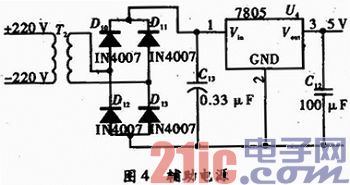
To prevent high frequency power circuits from interfering with digital control circuits, the system uses high speed optocouplers to isolate the two circuits. Therefore, the intelligent control circuit must be powered separately, and the auxiliary power module is shown in Figure 4. Use a small power AC transformer to step down the AC mains to 12 VAC, and use the L7805 to achieve a +5 VDC regulated output after rectification and filtering.
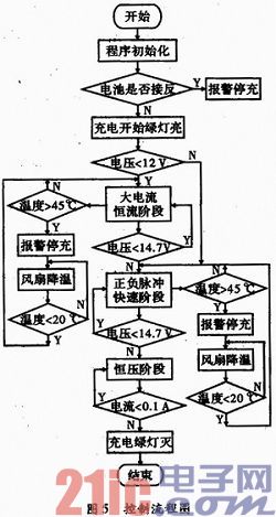
3 system software design system software main function: through the battery voltage, current detection to enter the corresponding charging phase, in the corresponding phase, the digital PI control algorithm is used to continuously adjust the PWM output duty cycle of the microcontroller to achieve The required constant current or voltage value. At the same time, the temperature value of the battery in each stage is detected. If it exceeds 45 °C, the alarm will be stopped and the charging will be stopped. At this time, the cooling fan is started, and the battery is cooled down until the temperature returns to within 20 °C. The specific control process is shown in Figure 5.
4 Conclusion The system uses single-chip digital PI control technology combined with high-efficiency, low-loss DC/DC conversion circuit. Due to the limitation of the operation speed of the single chip microcomputer, it is impossible to achieve accurate voltage and current output. However, the appropriate voltage and current ripple for the battery is beneficial to eliminate the polarization phenomenon during the charging process, and is more conducive to charging. Compared with the traditional constant voltage constant current charger charging, the developed smart charger has the following advantages: the charging speed is significantly improved, the charging is safe, the battery temperature is low, and the impact on the battery capacity and life is reduced; at the same time, the low-cost single-chip microcomputer is used. Instead of expensive power management ICs, intelligent management of power supplies makes them highly competitive in the market.
In this paper, the development and research of charging control and control strategy for 12 V/12 Ah battery are completed. The system and its control strategy have practical reference significance for the development and application of electric vehicle power battery charging system.
Digital currency transactions allow users to convert existing digital currencies into other digital currencies. The entire transaction does not involve any legal tender. Because of the relatively loose regulation, the mainstream digital currency trading platform also opened this function.Digital Asset Exchange (DAE) is a platform for matching transactions between digital currencies, digital currencies and legal currencies. It is the main place for encrypting the circulation and price determination of digital currency transactions.
Compared with traditional stock exchanges, digital asset trading platform not only matches transactions, but also plays the role of market maker and investment bank. The role of the market maker in the trading platform can increase the liquidity of the market, and the trading platform can earn the transaction price difference. The role of the investment bank of the trading platform is to provide services such as issuance and underwriting of digital currency, from which the trading platform collects money fees, or collects deposits in the form of community voting of the trading platform.
Currency Exchange,Digital Currency Exchange,Virtual Digital Currency Exchange,Display Currency Exchange
China youbi digital assets limited , https://www.ubcoinchina.com