The practical resistance active Wheatstone full-bridge sensor circuit of diffusion silicon pressure transmitter is introduced. The circuit principle is qualitatively analyzed, and the technical measures and performances such as zero point / range adjustment and migration, output signal feedback method, etc. are quantitatively analyzed. . 


Keywords: sensor, measuring circuit, electric bridge, zero point, range
The use of an electric bridge to form a sensor circuit for measuring differential pressure is a measurement method with higher sensitivity. The diffused silicon transmitter is mainly a resistance active Wheatstone full bridge pressure measurement circuit. It can make the transmitter more practical under the premise of achieving higher accuracy and stability, such as zero point / range adjustment and migration is convenient and fast. However, the introduction of diffused silicon bridge sensors in some literatures [1, 2] is too simple and limited to qualitative analysis. This article will quantitatively analyze the technical measures such as zero / range adjustment and feedback signal output stability used in the measurement circuit of diffused silicon sensors.
1 Working principle of sensor bridge
The sensor measurement circuit is shown in Figure 1. When there is no differential pressure, the currents of the two arms of the bridge are equal. The differential pressure signal is added to the four silicon varistors, and the resistance of the varistor changes with the differential pressure, causing the bridge to be unbalanced. The output voltage of the bridge is fed into the amplifier A1. The output voltage of A1 changes the magnitude of the output current I0 through the transistor Q8. I0 flows through the resistance feedback network of the bridge to restore the balance of the bridge. In this way, the change in the output voltage of the bridge is proportional to the change in differential pressure. Therefore, the change of the differential pressure is directly converted into an electrical signal.
2 Quantitative analysis and calculation
2.1 Measurement circuit and range adjustment
Figure 2 is a measurement circuit that includes a zero and span adjustment circuit, a feedback resistor network, and a differential pressure sensing bridge. The constant current source I0 represents the output current. The four bridge arm resistors are R1S, R3S, R4S and R6S. When the measured positive pressure increases, the resistance of R1S and R6S decreases, the resistance of R3S and R4S increases, and the output signal VBr of the bridge increases in the negative direction. This VBr corresponds to the voltage deviation signal of the measured pressure change value. After the role of the negative feedback resistor network in the measurement circuit, the VBr signal will remain very close to zero.
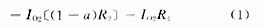
The basic feedback voltage formula is Vfb = V1-V2 = IO1 [aR2 + R1]
Corresponding to the upper range pressure of the sensor, the varistor and bridge give the maximum change and maximum unbalance. At this time, in order to keep VBr close to zero, the maximum feedback voltage value is required. When a = 1 and IO2 = 0 in formula (1), the Vfb value is the largest and the sensor gets the largest measurement range. When the range coarse adjustment screw is in the A position and the R2 sliding head is in the lowest position, the above requirements are met. When a = 0, IO2 is the largest, the measurement range is the narrowest. In this case, the three coarse adjustment screws are in the B, C, and D positions at the same time, and the R2 sliding head is in the uppermost part. Through the combination of the R2 sliding head and other positions of the coarse adjustment screw, the intermediate measurement range can be obtained. R2 has sufficient adjustment range to provide overlap between the range adjustment coarse adjustment screws corresponding to different coarse adjustment ranges.
The component of the feedback voltage Vfb at the output of the bridge is
2.2 Zero adjustment and migration circuit
Figure 3 is the basic bridge circuit plus the migration ± 100% circuit. Insert a 1000Ω resistor string between the two sides of the bridge. This series of resistors has six voltage output points to provide the required zero adjustment range. which is:
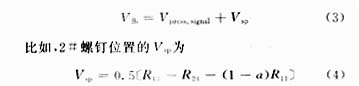
VBr = Vpress.signal-Vfb + Vsp (2)
Since Vfb is approximately equal to zero, there is
In the formula, a is determined by the position of the sliding contact on the zero potentiometer R11. It can be seen from formula (4) that different positions of the zero-adjusting potentiometer and screw correspond to different Vsp, which is why the output zero point can be adjusted. When the zero-adjusting potentiometer is at the upper end, a = 1, Vsp is the largest. The screw provides coarse zero adjustment, and the zero potentiometer provides fine zero adjustment.
references
1 Wang Jiazhen, Wang Junjie. Sensors and Transmitters. Beijing: Tsinghua University Press, 1996, 8: 85 ~ 86
2 Qiang Xifu. Sensor. Beijing: Mechanical Industry Press, 1998, 8: 44 ~ 46
BBQ Grill,Fashion Barbecue Grill,Stainless Steel Grill,Smokeless BBQ Grill
Shaoxing Haoda Electrical Appliance Co.,Ltd , https://www.hotplates.nl