Research on wireless positioning technology based on CC2431
introduction
GPS and other satellite navigation and positioning technologies are widely used in various fields. However, the positioning requirements in indoor, underground and other occasions have their limitations. In recent years, with the gradual improvement of the IEEE 802.15.4 commercial standards, the related technologies of wireless sensor networks (WSN) have been widely discussed and studied. Along with this, TI has proposed a system-on-chip (SoC) solution CC2431 with a hardware positioning engine. And WSN is widely studied in wireless positioning technology. The device can meet the application needs of low-power ZigBee / IEEE802. 15.4 wireless sensor networks. The positioning engine of CC2431 is based on the received signal strength indicator RSSI (ReceivedSignalStrengthIndicator) technology, compared to Centralized positioning system, RSSI function reduces network traffic and communication delay, in typical applications can achieve 3 ~ 5m positioning accuracy and 0.25m resolution. Based on RSSI positioning technology, the composition and positioning principle of the CC2431 wireless positioning system are introduced in detail, and the design based on the CC2431 wireless positioning system is implemented.
2CC2431 Introduction
CC2431 is supported by a powerful IAR integrated development environment, combined with the Zig-Bee protocol stack, toolkit and reference design, to show the leading ZigBee solution. Its products are widely used in automotive, industrial control systems and wireless sensor networks, etc., and are also applicable Other devices with a frequency of 2.4 GHz outside of ZigBee. The positioning engine of CC2431 is based on RSSI technology. According to the received signal strength and the known reference node position, the relevant node position is accurately calculated. Then send the location information to the receiver.
3 Based on CC2431 positioning principle and implementation
3.1 RSSI positioning technology
RSSI refers to the strength of the wireless signal received by the node. In the positioning based on RSSI, the transmitting signal strength of the transmitting node is known, and the receiving node calculates the propagation loss of the signal according to the received signal strength. Use theoretical and empirical models to convert transmission loss into distance. And further use the triangle positioning method to determine the location of the node to be located. The technical hardware requirements are relatively low, the algorithm is relatively simple, and some communication protocols already carry RSSI information, which makes the RSSI-based positioning method have wide application prospects. This technology shows good characteristics in the laboratory environment, but due to changes in environmental factors and other reasons. In actual application, further improvement is needed.
3.2 Positioning system based on CC2431
The positioning system consists of reference nodes and positioning nodes. The reference node is a static node at a known location. The node knows its location and can notify other reference nodes by sending data packets (using CC2430). The positioning node receives the data packet signal from the reference node, obtains the reference node position coordinates and the corresponding RSSI value and sends it to the positioning engine, and then reads out its own position calculated by the positioning engine.
The data packet sent by the reference node to the positioning node at least contains the coordinate parameter horizontal position X and vertical position Y of the reference node. The RSSI value can be calculated by the receiving node. Figure 1 is a block diagram of the specific positioning system.
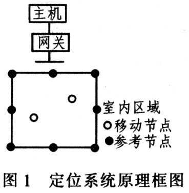
The function of each part in the functional block diagram of the positioning system is as follows:
(1) The host uses an ordinary PC, and the host connects to the gateway to schedule the work of the entire network. The positioning software is written to observe the operation of each positioning node and reference node in real time.
(2) Gateway The gateway is used to form a ZigBeeWSN network and act as a coordinator, transmitting positioning node coordinates and external environment parameters to the host.
(3) The reference node acts as a router in the network. And in the positioning system, it specifies fixed coordinates by the user, and provides the coordinates and RSSI average value for the positioning node. A reference node (referencenode) is a known static node whose coordinates (x, y) are fixed and do not participate in positioning calculations, and can be implemented by CC2430 or CC2431 devices. A positioning area usually consists of 8 reference nodes. The system needs at least 3 to 4 reference nodes to locate. This article uses CC2430 as a reference node to achieve.
(4) The positioning node has a positioning engine inside, which can calculate its own precise position (coordinates) based on the same coordinate and RSSI average value provided by the reference node, and sends the coordinate coordinate positioning node identification number to the gateway. The core device in this article is implemented with CC2431.
3.3 Positioning workflow
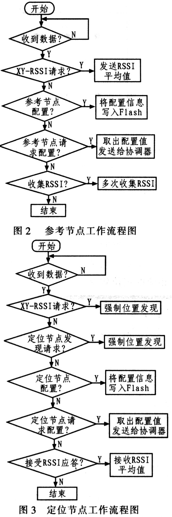
A positioning node (blindnode) is a type of movable node that can move arbitrarily within the area surrounded by the reference node. After receiving the RSSI values ​​of all reference nodes in the area, the positioning node calculates its coordinate position through the positioning algorithm. The positioning node south CC2431 device is realized. With this device, a positioning resolution of 0.25m and a positioning accuracy of about 3m can be achieved, and the positioning time is less than 40μs. Fig. 2 is a working flowchart of a reference node, and Fig. 3 is a working flowchart of a positioning node.
4ZigBee positioning system experimental results and analysis
Description of the experiment area: This experiment was carried out in the laboratory on the fifth floor of the teaching building: length × width = 8.13m × 8.10m. In this experiment, 6 reference nodes and 1 positioning node were used. The coordinates of each reference node are set as shown in the figure 4 is shown. The number next to the reference node is the node number, and the coordinates of the 6 reference nodes (the black ones are the reference nodes) are (in units of m) in order: 1 (8,000, 8.00), 99 (12.00, 8.00) , 101 (16.00, 8.00), 10 (8.00, 16.00), 16 (12.00, 16.00), 98 (16.00, 16.00).
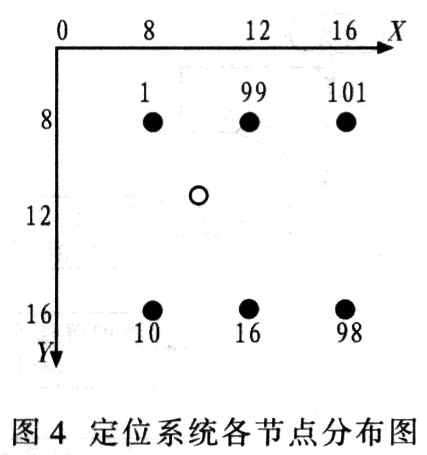
Table 1 is the data measured in this experiment, (x, y) is the coordinate of the actual location of the positioning node, (x1, y1) is the coordinate data of the positioning node measured by the GUI software of the host computer. A total of 21 sets of data were measured, as shown in Table 1.
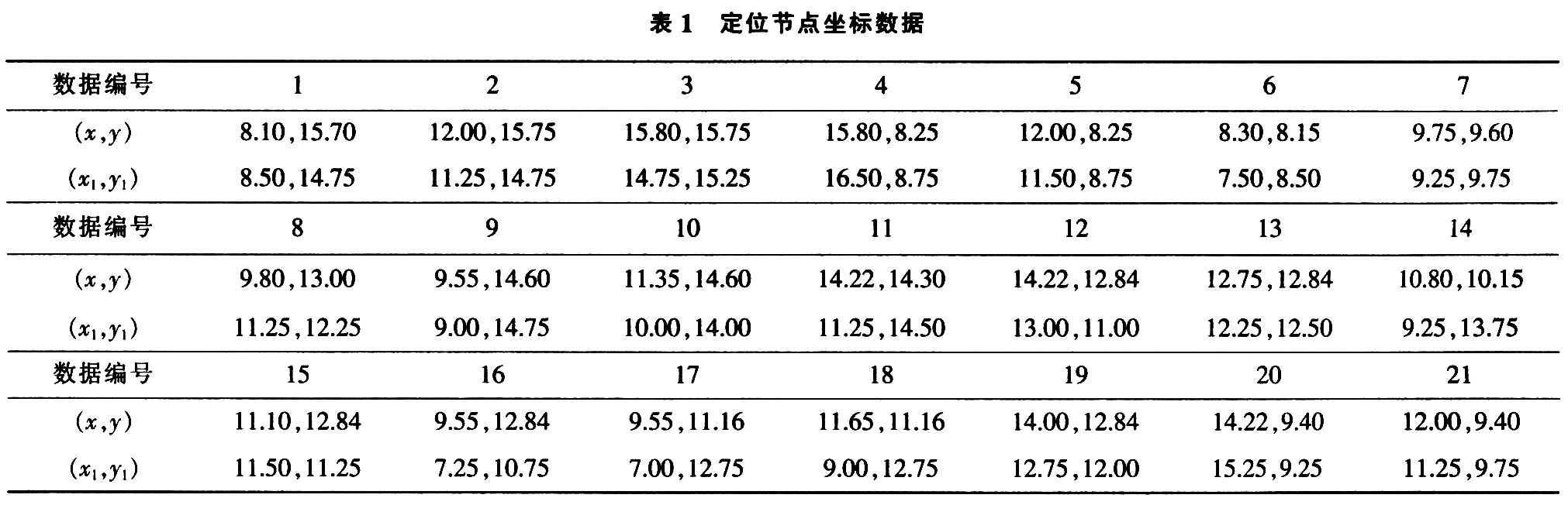
The data measured above is apart from the larger individual errors, such as the 11th, 14th, 16th, and 17th groups of data; the others are relatively close to the true position of the node. There are many sources of error. For example, when the positioning node is close to the wall, the error will be larger. The orientation of the antenna of the positioning node also has a greater impact on the size of the error.
Figure 5 is the interface of the host computer wireless positioning software ZWS_lum written according to the relevant communication protocol. The black dots represent reference nodes and the white dots represent positioning nodes. When the positioning node is close to or far from the reference node, the corresponding positioning effect can be clearly seen in the program.
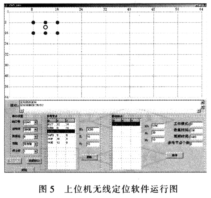
The software can not only display the actual networking information, but also: for the reference node, display its X, Y coordinates, and can modify the X, Y coordinates in the plane area, and then refresh to the topology map, so that it can be based on the actual The reference node needs to be arranged for the positioning area; for the positioning node, its real-time position information in the planar area can be displayed. The coordinate (x1, y1) information in Table 1 is obtained through the software. This information is updated every 5s. In addition, you can also view the positioning node configuration parameter information through this interface.
5 Conclusion
CC2430 / 2431 is a system-on-chip (SoC) solution for wireless sensor network ZigBee / IEEE802. 15.4. Its hardware positioning engine has the characteristics of low hardware equipment requirements and high positioning accuracy, which satisfies the market demand well. Using this method to establish an indoor positioning system by networking can achieve positioning accuracy within 1-2m. By arranging reference nodes reasonably, the system can be applied in buildings, underground, tunnels and other fields to achieve high-precision indoor positioning. Therefore, it is foreseeable that ZigBee-based wireless positioning technology will have good development and application in the future.
MOSO provide Dim-to-off Led Driver for energy-saving and circuit safety, supporting 0-10V, PWM, timer step dimming or DALI control, with low stand-by power. It is IP67, build-in surge protection, Class II design, power range 75W~320W. Dimming driver can adjust the output by programming software or controller which is isolated with diming signal.


This Dimming driver ensures cool operation and long life with extruded-metal housing and fully glue-potted. It is certified by CCC, CE, TUV, ENEC and CB standards, widely used in street lighting, flood lighting, industrial lighting.
MOSO has set several distributors in Europe, United States, Latin America, Asia and Australia. All MOSO Dim-to-off Led Driver provide 5 years global warranty. In case of any failure, customers can get replacement either from MOSO directly or any one of MOSO distributors.
MOSO always dedicates to providing professional outdoor lighting solutions. Please feel free to contact our sales team if you need any support!
Dim-to-off Led Driver
Dim-to-off Led Driver,Dim-to-off LED Dimmable Driver,Dimmable Dim-to-off LED Driver,Dim-to-Off Timer Dimmable LED Driver
Moso Electronics , https://www.mosoleddriver.com