1 Introduction
This article refers to the address: http://
High-tech applications have changed people's lives. As a basic vehicle, people also want to make driving operations easier and more convenient, and to communicate and communicate with the outside world in time.
Bluetooth technology can provide technical support for the realization of this new type of automotive electronic information system. Bluetooth technology can be used to wirelessly connect various electronic devices in a car to form a "vehicle network", which includes automotive electrical control equipment. , audio and video equipment, vehicle positioning and monitoring equipment, various sensors and their control systems, vehicle security systems and vehicle navigation systems.
As a new short-range wireless spread spectrum communication technology, Bluetooth has the characteristics of small size, low power consumption, openness and interoperability. Compared with the traditional transmission of data by cable and infrared, it has the following advantages:
(1) Strong anti-interference ability; when working with various electronic devices with wireless communication functions such as laptops and mobile phones for wireless Internet access, there is a large amount of electromagnetic interference to other electronic devices in the vehicle. Bluetooth technology features fast acknowledgment and frequency hopping schemes to ensure link stability. It divides the frequency band into several frequency hopping channels. In one connection, the radio transceiver continuously "jumps" from one channel to another channel according to a certain code sequence, and only the transmitting and receiving parties communicate according to this rule, thereby avoiding Interference; the instantaneous bandwidth of frequency hopping is very narrow, but this narrow bandwidth is spread hundreds of times into a wide frequency band by spread spectrum technology, making the possible influence of interference small. (2) No need to connect signal lines, reduce costs and reduce the space occupied. (3) It has the basic characteristics of electromagnetic waves, has a large power, can increase the transmission distance, and has no limitation of angle and directivity. It has wall-through property and can be reflected and diffracted between objects. (4) The power consumption is very low, and many components can be connected at the same time, and the transmission speed is fast.
The Bluetooth-based steering wheel control system introduced in this paper uses a network scheme combining wired and wireless to form the entire control system.
2 system design
The system realizes the control functions of constant speed cruise, sound, air environment inside the car, and headlight illumination in the car through buttons installed on the steering wheel.
The control system is designed based on Bluetooth technology, and its hardware components mainly include two main parts: Bluetooth master control device and Bluetooth slave control device. The master control device collects the button signal through the ZLG7289, and then sends it to the microprocessor STC89LE516 for processing. The microprocessor sends corresponding commands and data to the Bluetooth module BC219159B according to different button signals. The Bluetooth module is in the master and slave devices through the wireless network. The Bluetooth module transmits a command and data after establishing a link, and the microprocessor of the slave device sends different commands and data to the CAN bus according to the corresponding signal, and other vehicle systems connected to the CAN bus implement related functions according to the command, LCD Displays various functional statuses. The hardware block diagrams of the Bluetooth master and slave devices are shown in Figure 1 and Figure 2, respectively.
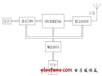
Figure 1 Bluetooth master device hardware block diagram
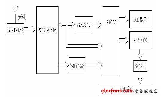
Figure 2 Bluetooth slave device hardware block diagram
3 system hardware design
3.1 main control equipment hardware design
3.1.1 Button section
The button position is shown in Figure 3 as divided into 4 zones with 4 buttons per zone. For a comfortable and simple operation, one-button multi-function is used to reduce hardware and simplify operation. 16 function buttons are set on the steering wheel.
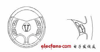
Figure 3 Location map of the steering wheel button
Function description: The 1st key is the fixed speed cruise switch button, press the 1st key to enter the fixed speed cruise control, press the 2nd key to enter the setting or reset function, the 3rd and 4th keys are the up and down options move key, and then press The No. 1 button exits the cruise control; the No. 5 button is the audio system startup and off button, and can switch between the FM/CD mode, according to the number of button presses (ON → FM → CD → Off), the No. 6 button is the program selection button, also based on The number of key presses selects related items, the 7th and 8th keys are the volume adjustment keys; the 9th key is the air conditioner start off button, the 10th key is the temperature mode switch key, the 11th and 12th keys are the temperature adjustment keys; the 13th key is the far and near light switch Control button, button 14 is the fog light switch control button, keys 15 and 16 are the headlight strength adjustment buttons.
3.1.2 Button Signal Processing Module
The key signal processing is realized by the keyboard scanning management chip ZLG7289. The ZLG7289 communicates with the microprocessor using the SPI serial bus. /CS, CLK, and DIO are connected to the three I/O pins of the microprocessor. The KEY is connected to /INT0, and serial data is sent from the DATA pin to the chip. Synchronized by the CLK terminal. When a key is pressed and the chip select signal goes low, the data on the DATA pin is written to the ZLG7289 buffer register on the rising edge of the CLK pin and is only allowed when the falling edge of the /INT0 pin occurs. Read the button value. In the absence of any button, the LED is in a bright state, and when any key is pressed, the LED is off.
Figure 4 and Figure 5 show the ZLG7289 chip pin diagram and keyboard logic array diagram respectively. The four row lines are connected to the SG, SF, SE, and SD pins of ZLG7289 respectively. The four column lines are connected to ZLG7289 data lines DIG0~3.
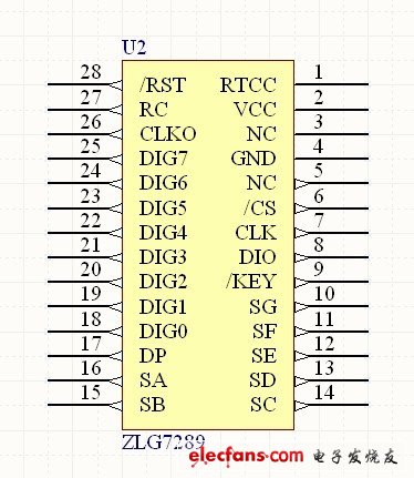
Figure 4 ZLG7289 chip pin diagram
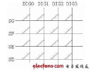
Figure 5 keyboard logic array diagram
3.1.3 Bluetooth module
The core of the BC219159 is CSR's single-chip RF chip BlueCore2–External, which includes the radio transceiver, baseband controller hardware circuitry and the protocols necessary to implement the Bluetooth application framework. On-chip auto-calibration and built-in self-test procedures simplify development, application, and product testing. When external Flash with CSR Bluetooth protocol stack software is added, BlueCore2–External forms a complete Bluetooth system for audio and data communication [1].
The off-chip components are few, the RF receiver has a near-zero IF structure, and the out-of-band cutoff performance at the low noise amplifier input allows the RF module to be used close to GSM and W-CDMA handset transmitters. The chip uses the FSK supervisor to provide superior performance in the presence of noise. The internal power amplifier has a maximum power output of +6dBm. The RF synthesizer is fully integrated in the core. No external voltage controlled oscillator, variable capacitance tuning diode or LC tuner is required. The system's reference clock is generated by the built-in crystal oscillator. The clock range is 8 ~40MHz.
The Bluetooth module supports various communication interfaces such as USB, UART, PCM voice interface and SPI interface. On-chip 32KB RAM, as a memory for the ring buffer and Bluetooth protocol stack function to save audio and data for each valid connection, and 8MB of Flash; support point-to-point and point-to-multipoint network topology, which can form a piconet and scatter network.
The Bluetooth module of this system converts the data into the corresponding Bluetooth code by the Bluetooth protocol. Since the BC219159 provides a standard UART interface, it can directly communicate with the UART port of the STC89LE516 in this system.
3.2 Control device hardware design
The control device hardware design includes Bluetooth communication, CAN bus control, display and other modules, which are limited to the following sections.
3.2.1 Bluetooth module
The slave device's Bluetooth chip BC219159 is connected to the microcontroller STC89C516. When Bluetooth starts working, its LED will flash rapidly. If the Bluetooth module of the master device is searching for the Bluetooth slave module at this time, the two automatically establish a connection and communication through the automatic search function.
Most of the controlled objects in the slave control system use the 5V signal level. Therefore, the STC89C516 single-chip microcomputer with 5V signal level is selected. Since the Bluetooth module uses 3.3V, when connecting the Bluetooth to the STC89C516, it is necessary to add a 100Ω resistor between the serial lines. Match the voltage.
3.2.2 CAN bus control
Modern car control system has many nodes, large quantity and high real-time requirements, and a large number of data information requirements can be shared among different electronic devices [2]. CAN bus is a serial multi-master controller LAN bus, which has High network security, communication reliability and real-time performance, simple and practical, low network cost, not only can reduce the wire connection, but also enhance the diagnosis and monitoring capabilities, suitable for automotive and general industrial environments. In this design, the CAN controller uses the SJA1000 of PHILIPS. The wiring of the in-vehicle system is shown in Figure 2.
3.2.3 Display Module
The display module of the system adopts ST7920 driver chip as the core 12864 liquid crystal display module, with 64*16 bit character display RAM and 64*256 bit drawing display RAM. The system will call the state mode and the function under the master device. The progress is displayed on the screen in real time in the form of pictures and characters. It has strong intuitiveness, which is convenient for the driver to know the parameters of various electronic devices in the car in time, making the control more convenient.
4 system software design
Software programming mainly includes two parts: Bluetooth communication software design and master-slave application design.
Initialize the Bluetooth module on the PC, set the master and slave, assign an address to Bluetooth, and determine its baud rate to complete accurate and timely data transmission.
BC219159 and STC89LE516 communicate through the serial port. In the program, the serial port function can transfer data to each other. Bluetooth is equivalent to an invisible wire, and the master and slave devices are connected.
4.1 Bluetooth communication software design
Data communication between two Bluetooth modules is achieved through HCI packets. HCI packets have command packets, event packets, and data packets. The data communication process generally includes the following six steps: Bluetooth module initial, HCI flow control settings, query, connection establishment, data transmission, and disconnection.
This part of the program is mainly developed in C language under the Windows XP environment by means of CSR's BlueLab development platform.
4.2 Bluetooth master-slave system application design
The application of the Bluetooth master and slave device is more complicated, and the software design follows the modular design idea. Figure 6 and Figure 7 show the flow chart of the main control and slave control systems respectively. All the program modules are developed in C language under Windows XP environment.
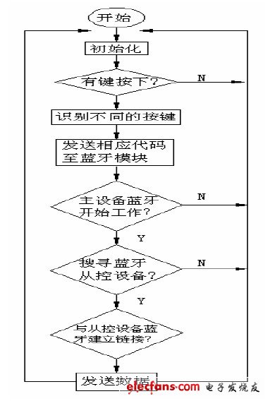
Figure 6 main control device flow chart

Figure 7 Slave device flow chart
5 Conclusion
The steering wheel control system designed by the above scheme has powerful functions, high cost performance, stable performance, convenient maintenance and easy development. Experiments show that the whole system has good versatility and scalability, and has application value.
A weak electrical cable is a cable used for security communications, electrical equipment, and related weak electrical transmissions.
Wire and cable refers to materials used in power, communications, and related transmission applications. There are no strict boundaries between "wires" and "cables." Generally, a product with a small number of cores, a small product diameter, and a simple structure is called a wire, a non-insulated wire is called a bare wire, and the other is called a cable; a conductor having a large cross-sectional area (greater than 6 square millimeters) is called a large wire. Small (less than or equal to 6 square millimeters) is called a small wire, and insulated wire is also called a wire.
Wire and cable mainly includes bare wires, electromagnetic wires and insulated wires for electrical appliances, power cables, communication cables and optical cables.
composition
It consists of an inner conductor, an insulation, an outer conductor and a sheath from the inside out;
Inner conductor: Since the attenuation is mainly caused by the resistance of the inner conductor, the inner conductor has a great influence on the signal transmission.
Insulation: affects attenuation, resistance, return loss and other properties
Outer conductor: return conductor, shielding
Civil Building Cable,Suspension Cable,Pvc Insulated Wire,Control Power Cable
Jiangsu QiSheng Cable Co., Ltd. , https://www.shuaihe-cable.com