Digital audio power amplification technology adopts a new amplification system. The power amplifier tube works in the D-type switching state. Compared with traditional analog power amplifiers, it has small size and high power. It is seamlessly combined with digital audio sources and can effectively reduce the transmission of signals. Interference, high-fidelity and other advantages have broad development prospects.
This paper presents an optimized design scheme for a high-efficiency digital power amplifier. The dual-band three-level natural sampling method (NBDD) pulse width modulation technology is introduced into the pulse width modulation design of the digital power amplifier, which reduces the design order of the low-pass filter and improves it. Signal-to-noise ratio; by introducing Dead TIme (dead time) technology into the design of switching amplifiers, the crosstalk loss and drain-source capacitance loss of switching amplifiers are reduced.
1 Implementation principle of optimization scheme
This scheme uses two independent channels, which can complete the digital processing and power amplification of the signal independently and simultaneously, and can be bridged into one channel for digital processing and power amplification of the signal. Each channel works in half-bridge working mode, and can be bridged into full-bridge working mode to work. Its implementation principle is shown in Figure 1.
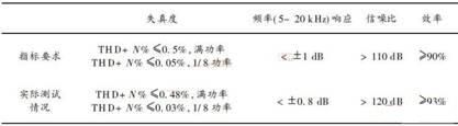
Figure 1 Schematic diagram of a high-efficiency digital power amplifier
The input analog audio signal is first amplified by an isolation amplifier and simultaneously low-pass filtered. The low-pass filter uses a second-order Butterw orth low-pass filter with a cut-off frequency of 37 kHz and a 3 dB bandwidth of 22 kHz. The filtered signal and the feedback audio signal are sent to the error amplifier for error amplification, and the amplified error audio signal is output. The amplified error signal and carrier signal are sent to the pulse width modulator, and NBDD modulation is performed to generate a PWM signal. The carrier signal is a high-linearity analog triangular wave signal generated by a triangular wave generator, and the frequency is adjustable from 230 to 280 kHz. The PWM signal is inserted into Dead TIme and then sent to the driver combining floating power supply and bootstrap for pre-amplification. The amplified PWM signal drives a half-bridge switching amplifier composed of field effect transistors for power amplification and outputs a power PWM signal. The PWM signal amplified by the switching amplifier is sampled as a feedback signal and sent to the error amplifier.
The power PWM signal is sent to a low-pass filter to restore the analog audio signal.
When it is necessary to bridge the output of a single channel, it is only necessary to feed the audio signal of the opposite amplitude at the input end of the two half-bridges, and connect the load to the output end of the two half-bridges.
In order to increase the reliability of the module, the design also considers the damage caused by various misoperations to the module, and provides a fault indication function to help the whole machine find the problem in time and accurately and facilitate the maintenance of the module.
2 Implementation of NBDD modulation technology
The specific implementation of NBDD modulation technology is shown in Figure 2.

Figure 2 NBDD modulation technology implementation block diagram
The input analog audio signal is first amplified by the isolation amplifier, and then sent to the error amplifier together with the feedback audio signal to output the amplified error audio signal. Send the amplified error signal and carrier signal to the pulse width modulator for NBDD modulation. The carrier signal is a high-linearity analog triangular wave signal generated by a triangular wave generator with a frequency of 230 to 280 kHz.
The focus here is to achieve a high linearity triangle wave generator and a high-speed comparator. The nonlinearity of the triangle wave will directly affect the linearity of the PWM modulator and the distortion of the whole machine; in order to restore audio well, the PWM switching frequency cannot be lower than 200 kHz, so a high-speed comparator is needed. The modulation method not only affects the performance index in the audio band, but also has a decisive influence on the high-frequency radiation performance (EMC) of the amplifier system. Therefore, from the audio input to the pulse width encoding link, the audio amplifier and error amplifier used should have high input impedance, low operating current, wide gain bandwidth, fast rise speed, good common mode rejection ratio, Low drift voltage and other technical indicators; the comparator should have the characteristics of fast response speed, low power consumption, and small input offset voltage.
3 Introducing the optimized design of the switching amplifier of Dead TIme
The main feature of the switching amplifier is high efficiency, so its optimized design should be mainly reflected in the further reduction of various losses, and truly reflect the characteristics of its high efficiency.
Based on the principle of crosstalk loss, you can think of a method for the gate drive voltage. After the upper tube is completely cut off, let the lower tube start to conduct, and after the lower tube is completely cut off, let the upper tube start to conduct, so that the crosstalk can be reduced Loss, at the same time can reduce the junction capacitance Cds loss. In order to solve the crosstalk loss, between the two drive signals, the delay is turned on and the principle of normal cutoff. The time added is called Dead Time (dead time). The principle is shown in Figure 3. The analysis in the figure is two N-channel FETs working on a switch arm.
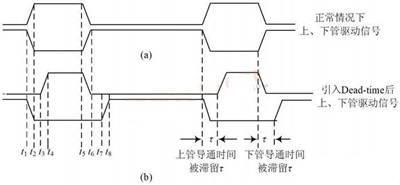
Figure 3 Comparison of signals before and after the introduction of Deed Time
4 Test of various indicators
The index test mainly adopts the Audio Precision System One which is a universal audio tester. Audio Precisio nSystem One is manufactured by Audio Precisio n Inc., the world's largest audio test instrument manufacturer.
The power supply is sent to the power socket of the prototype under test through an ammeter; the voltmeters are connected in parallel between the positive and negative terminals of the power output. The voltmeter and the ammeter are used to test the voltage and current output by the power supply, so that the output power of the power supply can be calculated. The audio input terminal of the tested prototype is connected to the audio output terminal of the audio tester, and the power audio output terminal is connected to the audio tester and the standard power resistor respectively. The power signal output by the tested prototype is sent to the standard load and sent to the audio tester Conduct analysis and testing. It is controlled by the computer to select the output signal frequency, amplitude and other characteristics of the audio tester Audi Precision Precision One, and the indicators to be tested are selected, and the test results are displayed on the computer.
Acid Filling Machine,Battery Acid Filling Machine,Acid Filling Machine Battery,Quality Acid Filling Machine
Zhijiang BSL battery technology service company , https://www.bslbatteryservice.com