The power line carrier walkie-talkie is not only different from the wired walkie-talkie (the audio signal is directly transmitted to the other party through the wire), but also different from the wireless walkie-talkie (the audio signal is modulated onto a high-frequency carrier. It is transmitted to the other party in the form of radio waves in the air), it It uses the principle of carrier communication to transmit carrier communication signals through low-voltage power lines (broadcast lines, CCTV signal lines, etc.). Wired carrier communication does not require a dedicated communication line, which will not affect the normal operation of the original line. It is more convenient and less expensive than wired communication, simpler than wireless communication equipment. It is easy to install and adjust, and has a high output power utilization rate.
The carrier intercom system introduced in this article has a total of eight intercoms (which can be expanded as needed), and you can call the other party without any transfer. Adopting the full-duplex communication mode (that is, double-reception and double-transmission), overcoming the general power carrier intercom, most of which use half-duplex (A- and B-reception or B-reception and A-reception) communication, which cannot listen and speak at the same time. At the same time using music calling, just plug the power plug of the intercom into the 220v mains socket. It is as convenient to use as an ordinary telephone. The circuit adopts the optimized design, which increases the transmission power, reduces the volume, and reduces the production cost. The call distance is 4-5km, which is very suitable for short-distance and small-range call contact. It is suitable for business production.
1. Working principle
The principle circuit of each walkie-talkie is shown in the figure. It consists of three parts: power supply, modulation transmission and reception demodulation. The 220v AC mains is stepped down by the power transformer T2, VD2-VD5 bridge rectification, and stabilized by the voltage regulator integrated circuit 7812 to 12v for the circuit power supply. C23 ~ C25 are power filter and noise elimination capacitors, and LED8 is the power indicator LED.
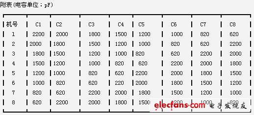
The modulation transmission circuit is composed of a microphone MIC, a music call circuit, an audio amplifier, and a filter oscillation circuit. VT1 and VT2 are modulation tubes and S1 is a call button. UM66 is a music integrated circuit (commonly known as a music triode). The step-down resistor R8 can make its ② foot obtain a suitable working voltage of 1.5-3.5V. R7 is the bias resistance of the microphone MIC. After the language signal is converted from the MIC into an electrical signal (or the music call signal generated by pressing S1), it is sent to the A amplifier of the TDA4920 via the coupling capacitor C12 from the ③ pin. R5, R6, C13 are negative The feedback element, the amplified audio signal is output from the ①pin, and sent to the modulation tubes VT1 and VT2 via C11 and R4 to amplitude modulate the high-frequency carrier oscillation signal. VT3, C1 ~ C7, T1's L1, L2, etc. constitute a carrier oscillator, the oscillation frequency range is 100 ~ 320kHz, the modulated carrier signal is selected by the parallel resonant circuit composed of C1 ~ C7 and L1, which is composed of L4, C20, C21 Send to 220v power line for long distance transmission. The eight walkie-talkies that make up the communication network each have seven different sending frequencies and a fixed receiving frequency. The receiving frequency is determined by C8 and L3 parallel resonance frequencies, and the call sending frequency is selected by S1-1 ~ S8-1 Synchronous linkage switches S2-2 ~ S8-2 make the LEDs LED1 ~ LED7 light. Display the called phone number.
The receiving demodulation circuit is composed of receiving detection and audio power amplification circuit. The other party's music call or send signal is coupled to L3 through the power line and L4 of T1. The frequency signal of this unit is selected through C8 and L3, and the audio signal is demodulated by the detection circuit composed of VD1, C18, C19 and R11, and the volume and potential The RP and C14 are sent to the B amplifier in the TDA4920 for power amplification, which pushes the speaker BL to sound. R9, R10, C15 are feedback elements. C16 is the output coupling capacitor, and C17 is the power filter capacitor of TDA4920.
2. Component selection
VT1 selects small power transistors such as 2SA1015, which requires PCM≥300mw and β = 40 ~ 60. VT2 selects 2SC2228 transistor, RCM≥500mW, β = 80 ~ 120. VT3 is the key to production. To increase the communication distance, Pcm≥750mW and β≥150 are required, such as 2SC1941, 3DA87B, 3DG27B, etc. Power amplifiers A and B use dual audio amplifier TDA4920. Its working voltage is 3.5 ~ 13.5V. Rated output power Po = 3W & TImes; 2. S2 ~ S8 use double interlock switch, BL uses 16Ω or 32Ω speaker, the power is greater than 4w. MIC uses ordinary electret microphones, such as CRZ2-9, -15, -16, etc. In order to simplify the circuit, LED1 ~ LED7 use domestic voltage light-emitting diode BTV344052 with current limiting resistor. Its working voltage is 12V. The luminous intensity is greater than 2mcd. High-frequency choke coil L5 can use finished inductor of 10 ~ 22μH. Oscillation transformer T1 needs to be self-made, choose MX-400 medium wave magnetic core, Y10mm & TImes; 50mm (round) or B4mm & TImes; 12mm & TImes; 50mm (flat), L1 ~ L4 are wound with ΦO.2mm high strength enameled wire: L1 and L3 Around 20 turns, L2 around 12 turns. L4 around 55 turns. Call the music integrated circuit UM66. You can also choose according to your preferences. Other elements are marked as shown in the drawings, C1 ~ C8 see the attached table.
3. Debugging method
The debugging method is relatively simple, mainly to adjust the working point of the oscillating tube VT3, that is, to adjust R1 to make the collector current of about 70mA. If the vibration cannot be started, the two ends of L2 can be adjusted. Then use the fine-tuning capacitor and adjust it repeatedly at both ends of C1 ~ C7 and C8, so that the signal received by this machine is the clearest, the communication distance is the farthest, and the network calls between several machines do not interfere with each other. Due to component error and T1 winding is not standardized. As long as it does not affect the normal conversation, slight crosstalk is allowed.
Shaoxing Tianlong Tin Materials Co.,Ltd. , https://www.tianlongspray.com