1. introduction:
Dust-free paper (also known as puffed core material) is a new type of high value-added hygiene products. It has the advantages of excellent high moisture absorption, reliable water retention, sanitation and safety, and is widely used in women's sanitary napkins, adult urinary incontinence, baby diapers and other product fields.
Because DeviceNet is based on the producer / customer network model, it enables control data to reach all site units on the network at the same time, and the network utilization rate is high; it allows the transmission of state switching messages, which can achieve faster response and effectively reduce Network traffic. Periodic message transmission provides better certainty; peer-to-peer communication allows data and status information to be exchanged between devices; these advantages provide a strong guarantee for higher productivity.
2. Open network control structure of dust-free paper production line:
Our company's dust-free paper production line is imported from Europe. It is the most advanced equipment in the industry. Its control system absorbs the full-scale automation concept of Rockwell Company of the United States and runs through all levels of its Netlinx system.
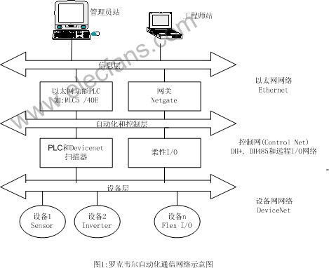
Figure 1 Rockwell Automation communication network diagram
Realized a seamless connection from the information layer (Ethernet) to the control layer (ControlNet) and the field layer (DeviceNet). As shown in Figure 1.
Dust-free paper requires stricter production process conditions. It belongs to a dry papermaking (Dry Forming) process. The basic process is: the crushed wood pulp, fiber, SAP, PE powder and other raw materials are uniformly formed through the molding station in an environment of constant temperature, constant humidity, and constant pressure, and then subjected to glue spraying, heating / melting, hot pressing, and cooling , Slitting, rolling and other processes to produce qualified products.
The control layer of our company's production line includes a total of nine AB PLC5 (eight) and AB SLC500 (one) programmable logic controllers with Ethernet function. They are controlled separately: air conditioning (Main Air condiTIon), raw material preparation (Raw material preparaTIon), uncoiler (TIssue Unwinder), hot oil heating system (Hot oil System), filter packaging system (Main Filter system), main line control system ( Nine process areas including Main Line and Reel.
Six of these PLCs are installed in the PLC control cabinet in the MCC1 room of the motor control center in the middle of the plant. The Ethernet interface of each PLC is connected to the hub (HUB) in the PLC cabinet through twisted pair. The other three PLCs are installed in the control cabinet of the equipment site, and their Ethernet interfaces are also connected to the MCC1 hub (HUB) through optical fibers.
Five AB industrial PCs equipped with RSview32 software are installed in the central control room. Their Ethernet interfaces are connected to a HUB in the central control room, and then connected to the HUB in the PLC cabinet through an optical fiber. The network is also connected to the enterprise intranet through the HUB. In this way, the Ethernet network is formed through the TCP / IP protocol, forming the information (management) layer. (As shown in Figure 2 below: Schematic diagram of the control layer and information layer network)
In addition to connecting local and remote I / O modules, Panel View man-machine interface and other devices, each programmable controller is mostly installed with DeviceNet scanner (1771-SDN or 1747-SDN), and through DeviceNet communication module (1336 -GM5, 1203-GK5, 1794-ADN, etc.) off-site smart devices, such as frequency converters, motor soft starters, Flex I / O, 9000 series photoelectric switches, etc., constitute a DeviceNet device network, which realizes the effectiveness of field-level devices control.
3. DeviceNet functions and features:
DeviceNet is a field bus based on CAN-BUS technology. It is an open communication network that conforms to the IEC61158 international field bus industry standard.
DeviceNet is used for the communication network between the field device and PLC, the transmission rate can be set to 125, 250, 500KPBS, the maximum transmission distance is 500 meters, and the maximum number of nodes (sites) is 64, allowing online configuration and hot plugging with electricity .
DeviceNet supports master / slave, multi-master, pair, etc. communication methods. The user's PLC can use the control program and the data of the upper PC to effectively monitor the field devices through the DeviceNet network.
DeviceNet can use Rockwell's RS Networx for DeviceNet or DeviceNet Manager software for network configuration and management.
The DeviceNet network has a simple structure and strong real-time performance. It uses the producer / customer model and provides powerful fault diagnosis and troubleshooting capabilities. It is an ideal device-level fieldbus.
4. The physical structure of the Devicenet network of the dust-free paper production line.
My company's DeviceNet network uses four AB PLC5-40E and one SLC5 / 04 as the host. DeviceNet scanner modules (AB 1771-SDN or 1747-SDN) are installed on the local rack of the PLC. The 1771 scanner has two channels, and each channel can connect up to 64 stations (usually 63). Each PLC uses the local network scanner to connect each fieldbus device in this control area through the DeviceNet communication adapter (1203-GK5, 1336-GM5, 1794-AND, etc.). These sites mainly include: AB frequency converters (1336F, 1336E, 160SSC series), A-B motor soft starters (SMC 150 series) FLEX I / O (1794 series); ARMOR Block protective I / O components, 9000 series photoelectric Switch etc.
The typical DeviceNet network adopts the physical structure of trunk / branch line. My company uses the DaisyChain (DaisyChain) circular connection form, using Belden standard round five-core shielded communication cable to connect each site. (As shown in Figure 3 below, the DeviceNet device communication network of Daisy Chain; take the inverter network as an example)
Due to the scattered distribution of equipment in our factory, some sites are far apart. In particular, some on-site sites are more than 100 meters apart. Therefore, the transmission rate of all DeviceNet networks is set to 125KBPS to ensure reliable communication. In addition to distributed I / O, man-machine interface and sensors, and other sites are located outside the production site, the DeviceNet network system of more than one hundred inverters is distributed in two motor control centers (MCC) rooms, which realizes centralized control of the motor , Unified management. (As shown in Figure 4: A corner of the MCC indoor DeviceNet inverter network Note: The yellow cable in the figure is the network communication cable)
Between the various workstations of DeviceNet, we mostly use open-type sub-interfaces (Note: some stations on the site use sealed T-type sub-interfaces or sealed connection ports) to connect power lines, communication lines, and shielded lines between stations. Separately and connected together to form the physical topology in the form of a daisy chain. Terminal resistors were installed at the first and last terminals. (121Ω, 1%, 1 / 4W)
5 DeviceNet configuration software and control realization.
Use the PC interface of the device network RS-232-C to adapt the human machine (1770-KFD) or the device network PC card (1784-PCD) to realize the communication between the PC and the device network scanner of the PLC.
DeviceNet management software RS Networx for DeviceNet is software based on the Windows platform, which can be used to configure the device network and perform project management and network fault diagnosis. It supports AB and third-party device configuration electronic data sheets (EDS).
The DeviceNet protocol defines two different types of messages: explicit messages (Explicit Message) and I / O messages (I / O Message). Both messages can be transmitted on the bus at the same time.
During the configuration process, first, the scanner should be configured, the I / O address interface between the scanner and the PLC should be set, and the communication between the scanner and the adapters of each station should be established.
When configuring each station on the network, first define the address (ie, station number) of each station. The address of the station may not be continuous, but it must be consistent with the setting of the DIP switch of each station adapter.
For I / O type workstations such as Flex I / O or Armor Block I / O, we use the form of I / O messages (I / O Message) to distribute the input and output of each station. I / O messages are transmitted periodically and have a higher priority, thus ensuring its real-time performance.
For equipment sites such as inverters, soft starters, etc., we use the form of explicit messages (Explicit Message) to distribute the word length sent / received between the PLC and each station; define the communication method and (we define the polled method, Each scan cycle); Establish the corresponding "soft" I / O relationship with PLC.
Then use the programming software RSlogix5 of PLC5 to compile the block transfer (BTR / BTW) command to realize PLC to collect and control the I / O information of the equipment online workstation. The PLC control program can issue control commands to each station according to the working status of each station to meet the technological requirements.
Since all PLCs of our company are connected to Ethernet, there are Rsview32 monitoring workstations in the control room on the Internet. Each display can show the monitoring interface of different process areas of RS view. In the central control room, you can not only control the equipment of the whole plant, but also check the current working status of each station. The man-machine interface is very friendly.
6. Experience of using DeviceNet network.
(1) DeviceNet fieldbus can save a lot of costs.
From the installation stage, only one communication cable is used to realize power supply and communication for all sites on the entire network. Compared with the point-to-point control method, a large number of cables and bridges are saved. Not only shortens the installation time, but also reduces the installation cost.
From the point of view of control: the use of network communication and "soft" I / O mode also saves I / O modules and large sums of money.
Such as the inverter workstation, start / stop, acceleration / deceleration and other commands; voltage, current, temperature and other parameters can be realized from DeviceNet network communication, saving I / O modules, especially analog I / O modules, the cost is quite expensive .
(2) The equipment failure rate is greatly reduced, and the diagnosis is convenient and the elimination is rapid.
DeviceNet only uses one communication cable to control the entire equipment network, which greatly reduces the equipment failure rate. The communication terminals of each site support live hot swapping. If a site has problems and troubleshooting, it will not affect the normal operation of other sites on the network.
Using data communication to control each station not only greatly reduces the number of traditional point-to-point cables, but also greatly reduces the number of fault links and further improves the system stability.
The form of centralized control of MCC is very effective through the equipment network, which greatly facilitates the diagnosis of equipment failure. For example, for the control of inverters, due to the use of MCC and network control methods, there are only five typical control circuits for more than one hundred inverters, which is convenient for memory and fault finding. When a certain inverter fails, not only can you see the alarm information from the main control room, but also you can get the alarm information from the network scanner or the man-machine interface of the inverter, which is convenient and fast.
(3) System monitoring is more convenient and intelligent.
Through the RSview monitoring interface, the central control room can access and control some sites on the equipment network at any time, adjust the control parameters as needed; and can monitor the working status of the equipment on the network, such as motor current, temperature and other parameters, to ensure that the equipment works normally.
7. Experience of DeviceNet network maintenance and troubleshooting:
(1) Communication interference
During the operation and commissioning phase of our plant, the status display of some sites (RSview man-machine interface in the control room) and its actual working status sometimes are inconsistent or the control command execution is not strict. After diagnosis and analysis, we have mainly taken the following measures.
1). Check and tighten each terminal resistance to prevent signal reflection.
The terminating resistor is used to prevent (reduce) the reflection of communication signals. In order to check whether the terminal resistance is working properly, you can measure any two CAN-H (blue lines) and CAN-L (white lines) on the network when the power is off (only during preventive maintenance or system failure) The resistance between the terminals should be about 60Ω-70Ω (because our factory uses a daisy chain structure).
2). Reliably connect the grounding wire of the DeviceNet network to eliminate external noise interference.
To prevent circulating currents, the shield of the signal cable can only be grounded at one end. The ground point is best drawn from the physical center site closest to the network to achieve the best results and maximize the elimination of noise interference. The ground wire of our factory is drawn from the scanner site of the PLC rack.
The grounding method is: connect V- with Shield and Drain with PE reliably
Through 1), 2) the above two methods and regular PM inspection can ensure that the network communication system works well and reliably.
In addition, in order to ensure reliable communication, the following should be noted when wiring the network:
1). In order to avoid the interference of communication cables with power cables, the communication cables should be routed separately. If the communication cable and the power cable share the wire groove, the communication cable should be routed through a metal shielding tube.
2). If the stations are far apart or the total network distance is large, thick-core communication cables should be used.
(2) If the equipment of a certain site fails, and the spare parts of the same model are not replaced in the inventory, it may cause trouble.
If there is a failure at a certain site of the equipment, the spare parts of the same model are in stock. After replacing the spare parts of the same model, the station can work normally. If the spare parts of different models are replaced, the physical station (EDS) detected by the network scanner is inconsistent with the scan list. The scanner will have an alarm and the station will not work properly. At this time, you have to reconfigure the scan list and download it to the scanner before this station can work normally. This is a problem that should be noted.
8. Conclusion:
The clean paper production line uses DeviceNet fieldbus control technology, which greatly improves the reliability and real-time performance of the control system. The use of fieldbus technology for automated control of production lines is an ideal solution. The significant advantages of fieldbus technology determine that its wide application is an inevitable trend in the field of control.
Jiangmen MagicPower Electrical Appliances Co.,Ltd. , https://www.magicpowerfan.com