In the dimming and control of luminaires, the DMX512 control protocol was widely adopted. It was proposed by the United States InsTItute for Theatre Technology (Inc) in August 1986 to transmit 512 on a pair of lines. The standard of the thyristor dimming brightness information; the DMX512 communication mode adopts the asynchronous communication format, and each dimming point is composed of 11 bits, one of which is a start bit, 8 bits of dimming data, and two stop bits. Each transmission can have 512 dimming points. EIA485 (RS485); DMX512 is designed around the industry standard EIA485 interface. EIA485 belongs to the "electrical" end of interface, voltage, current and so on.
The DMX512 controller can output standard DMX512 control signals. The DMX512 controller can output standard DMX512 control signals. It can cascade multiple DMX lamps and can be combined with LED DMX drivers to form a complete DMX control system. In large LED outdoor decoration projects. The control system consisting of DMX512 controller and DMX driver has been widely used. At present, the DMX512 controller in China usually has a 3-pin XLR interface. This is very bad. It is used in foreign countries with 5 pins, so it can be distinguished from the audio cable!
Dmx512 controller - the main componentsDmx512 controller is an important circuit control component, which will be used more widely in many occasions. It is very important for the user to understand the components of the device. Let's analyze dmx512 with everyone. The components of the controller can provide users with more in-place performance when purchasing equipment, and provide some help for everyone's purchase. Generally, when designing equipment, the modular design is very good. What are the components of this equipment? Please see the following paragraph;
Dmx512 controller components: CPU module function description
In fact, we can know from this name, the CPU refers to the central part of the device, and also the computing part of the device. In the process of using the general device, we will use the corresponding single-chip microcomputer as the basis, which can ensure that the data signal is not connected. The influence of any factor, while using the peripheral circuit to provide the corresponding clock calculation, the input of the CPU central module and the processing frequency of the information can be well assisted without any interference.
Dmx512 controller components: RGB module
In the process of using the device, the RGB module is an important guarantee for the use of the device and an important basis for color. It is worth mentioning that the PWM module is used in the center of the device to help improve the device, and different color schemes are Record to help the device to better connect. The RGB module is a good accessory for the device to illuminate. This design is a good way to assist the device to use it better.
Dmx512 controller components: button module
In order to help the device to make the necessary parameter settings, the button module is also an important part of the device. Generally speaking, the device selection is mainly based on simplicity. This design can assist the device to make necessary use and facilitate different devices. It is used at the same time, and there are also many improvements in operability.
Dmx512 controller - design standardThe DMX512 is designed around the industry standard EIA-485 interface. EIA-485 is the "electrical" end of the interface, voltage, current, etc.
The system is based on a downward symmetric transmission along the twisted pair of shielded conductors. This winding structure ensures that the resulting interference acts equally on both signals, thus ensuring consistent digital phasing. The wire used should be a suitable data conductor consisting of one or two twisted pairs, foil and braided screen. Symmetric audio wires cannot do this.
Normally, as with any segment, there should be two terminals at each end of the wire. The lighting console usually has a terminal at one end and a 120Ω resistor at the other end. The EIA485 specification only supports "daisy chains" or a serial network of up to 32 "cell loads" per segment. The manufacturer claims that each segment can be as long as 1000m. However, it is important to point out that the role of the repeater should be considered to be around 700m or 800m, which can prevent environmental anomalies.
Dmx512 controller - DMX lighting control system application designDMX512 lighting controller has been widely used in the field of LED control. The technology is quite mature and highly reliable. The control system developed based on this paper has been realized and the products have been widely used in the market.
Let's take a look at the implementation path of this solution.
Figure 1 shows a typical DMX lighting control system. The PC host uses the lighting control system to set the display scheme and output it to the DMX control system through the DMX console. The green part of the figure is the content of this article, and other nodes in the system will be described in other articles.

Figure 1 DMX lighting control system
1, hardware implementation
System hardware block diagram shown in Figure 2 system hardware block diagram:
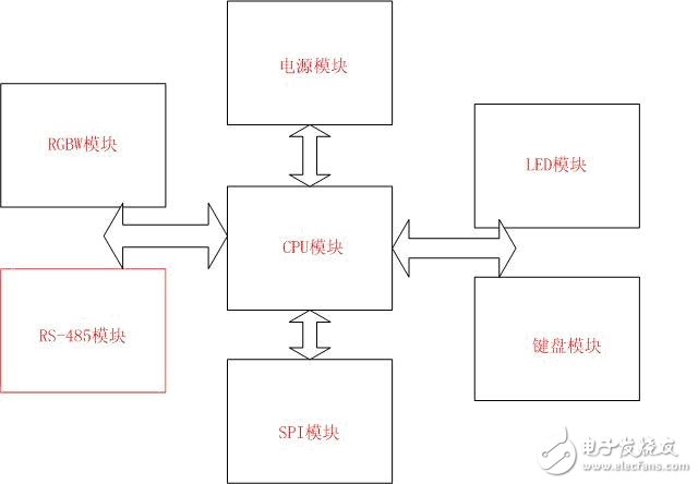
Figure 2 system hardware block diagram
2, CPU module function description
The CPU module is the main part of the system. The CPU controls all the functions of the system. The system uses the PIC18F4431 microcontroller as the controller. The peripheral circuit is clocked by a 10M crystal oscillator. At the same time, it is compatible with the design. The clock input can be directly provided by the clock chip MAX7381. The circuit is shown in the peripheral clock circuit of Figure 3.
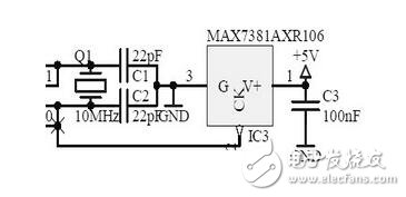
Figure 3 peripheral clock circuit
3, RGBW module
This module is controlled by the PWM module of the CPU to realize the control of the LED RGB full-color lamp to achieve different color display schemes.
The circuit structure of the module is simple, the corresponding RGBW four-channel output is respectively connected to the four PWM output I/O pins of the CPU, and the PWM module outputs corresponding pulse waveforms to control the opening and closing of the four MOS tubes, thereby Get different color schemes.
4, button module
It is used by the user to set related parameters. This function is not used in the current version. Each button is pulled up directly to the I/O pin of the CPU by pulling up the pull-up resistor.
5, wireless receiving module
This module is used to receive the control signals from the supporting wireless remote control to facilitate the user to set and test the relevant parameters.
This module uses the wireless transceiver chip dedicated to KEYMARK of Taiwan. The module uses Manchester code. In this system, it is a receiving chip. The chip interface is simple, only one I/O is needed to receive the signal, and the signal processing is completed by software.
6, RS-485 module
The RS-485 receiving module is used to implement the DMX512 protocol, and the physical layer interface used by the DMX512 protocol is the RS-485 interface.
This module uses the universal 485 interface chip MAX487 to realize the level conversion of the RS-485 interface and the UART serial port of the single chip microcomputer. The interface circuit is shown in Figure 4, the MAX487 peripheral circuit.
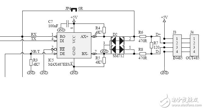
Figure 4 MAX487 peripheral circuit
7, power module
This system control not only supplies power to the controller but also supplies power to the external RGB strip. Therefore, it must use a high-power power supply. The power supply voltage can support a variety of power supplies, 48V, 24V, 12V, etc., and support voltage detection and Flow detection. The power module input is AC 220V/50-60HZ. 5V and 3V power supplies are required inside the module. 5V is converted using HVLM2594, and 3V is converted from 5V using AS1117 to power the wireless module.
8, software implementation
This system uses PIC18 microcontroller, the compiler is PICC18 8.35PL2, C language programming. The system software block diagram is shown in Figure 5 system software block diagram.
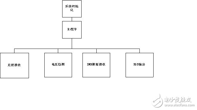
Figure 5 system software block diagram
among them:
1) The wireless receiving module is implemented by an external interrupt function to implement Manchester decoding.
2) Voltage detection is realized by A/D conversion, which is used to detect the supply voltage. If the supply voltage is too low or too high, it will enter the corresponding protection.
3) DMX data receiving is realized by serial port interrupt. The DMX512 protocol is implemented by software. After detecting the DMX512 data frame, the data is put into the buffer and the corresponding flag is set.
4) The RGB output is controlled by the timer interrupt function. When the timing is up, the corresponding flag is set, and the RGB output is refreshed according to the current RGB buffer data.
Aluminum Laptop Stand, eight highlights, powerful functions, bid farewell to the sultry heat, and welcome the cool moments of summer. Desktop Laptop Stand Adjustable height, hollow heat dissipation, block angle design, multiple compatibility, strong stability, portable and easy to carry. Portable Laptop Stand guiding a healthy posture to raise your head to work, a small figure is great for magic, unlock a new posture, you can put mobile phones, tablets, books, computers.

Laptop Stand Upright,Desktops Laptop Stand Upright,Laptop Support Adjustable Upright,Alloy Upright Laptop Stand
Shenzhen ChengRong Technology Co.,Ltd. , https://www.chengrongtech.com