The origin of the 6H30 tube is the Soviet Union. The 6H30 belongs to the frame grid type electronic tube. It uses a three-layer mica root bracket as an auxiliary support super-reinforced structure. It highly strengthens the seismic resistance and has a life span of 10,000 hours. At that time, it was applied to the fighter "Su-27", and the mechanical structure was highly strengthened. At the same time, its electrical characteristics were about two 6DJ8 / ECC88 in parallel, the transconductance was extremely high, the output current was large, the output impedance was low, and the ultra-low Silent, almost no microphone effect, a bit like the Telefunken E182CC tube with excellent appearance, as long as the simple conditions can play a great effect. Only because it was Soviet military supplies, the ban was lifted until the end of 2000, and was known to amplifier manufacturers and enthusiasts.
The well-known ARC in American tube amplifiers uses 4 6H30s in the newly launched Audio Research 3, which is quite indicative. It is well known that this Hi-End brand has always specialized in 6922 / 6DJ8 vacuum tubes. To the latter level, it has been planned and designed around 6922 / 6DJ8 for decades. Now it is switched to 6H30 in its top reference series. If it is not excellent, it is in line with its technical indicators. I am afraid it is difficult to be selected. And another well-known brand in China-Ober, in its reference level Reference CD2.3 advanced CD turntable system, the RCA output signal part also uses the buffer circuit constructed by 6H30 as the output. From the above two examples, you can know the excellent performance of 6H30. Of course, the price of this tube is also relatively high, but compared with the antique tube of thousands of yuan, the price of two hundred yuan is still not very expensive. At present, there are ordinary models of Sovtek, gold feet and EH that can be purchased in China. There are three types of gold feet, the supply is sufficient, and the quality is also proven. It is a pipe that is worth exploring its potential.
I searched the circuit about 6H30 on the Internet. The single-tube amplifier circuit found two self-sufficient bias circuits with a constant current source as a load; an amplifier circuit for Italian enthusiasts that uses fixed bias and inductive loads. Screen output circuit; DIYZONE also uses a constant current diode as the load test circuit, and also found a 6H30 single-tube amplification simulation software that can display the characteristic curves of various operating points, so it is very convenient when designing the circuit
Design Concept:
The initial assumption is a single-tube screen output, self-generated bias, and screen current load.
The screen output is mainly considering that there is no gain in the output of the cathode follower, and the blasting may not be able to withstand the explosion, and the power of 6H30 cannot be fully exerted. Although the fixed bias can flexibly select the operating point, it needs to add input coupling capacitors, which increases the circuit adjustment variables, and a good pair of coupling capacitors is also valuable. The adoption of the constant current source, one is helpful to use the gain of the spontaneum, the second is to read the Japanese tube machine books recently, and found that the constant current source is widely used in the circuit of Japanese enthusiasts, the overall evaluation is a good chance more some.
The circuit structure of the constant current source is many, and the common ones are as follows: constant current diode, field effect tube, LM317, light-emitting LED (diode, TL431) and crystal transistor, operational amplifier and crystal transistor, electron tube, transistor and electron tube, The mixed use of field effect tubes and electron tubes, integrated circuits and electron tubes, etc. is limited to space, and will not be described in detail here, and a full analysis will be prepared later in another article. Considering that the 6H30 panel load needs to withstand a relatively high voltage, at the same time, I hope to add some pentode-specific sound stains, because I have seen foreign models with pre-level design circuits in the past, 6080 for single-tube circuit amplification, EL34 for constant According to the source, the original author believes that the frequency response of the triode is relatively straight, and the ends of the high and low extensions are better. The sound of the pentode is condensed and the resolution is strong. The mixing of the two characteristics should be a perfect sound. Affected by this article, so I plan to use a constant current source circuit composed of 6BQ5 (6P14, EL84).
I just met a Mr. Li in Taipei when I was searching for information on the Internet. Mr. Li was a repairman of ARC Taiwan agent. He has 30 to 40 years of experience in repairing top audio equipment. The amplifiers are very familiar with him. He talked about the 6H30 tube and his own ideas. He soon drew a circuit diagram of the 6H30 and 6BQ5 combination. See Figure 1. Of course, this circuit is strictly speaking, it can not be considered constant. Current source, but a similarly deformed SRPP structure, because the gate and cathode of 6BQ5 are connected to the 6H30 screen. When 6H30 input AC, its screen current will change, and the working current of 6BQ5 will also change. The SRPP circuit with asymmetric impedance has different upper and lower impedances, the midpoint output is not half of the B + voltage, and the maximum output clipping is not the same as the upper and lower clipping, so it can only work similar to SRPP.
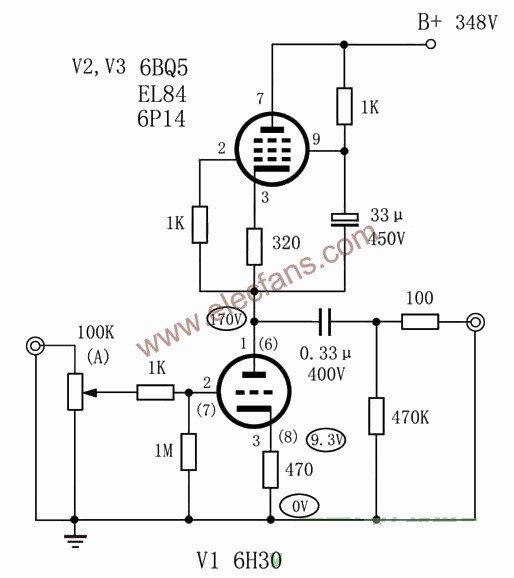
The initial setting of several resistance values ​​in the figure:
First set the working voltage of 6H30. According to the original factory data of Figure 2, the following working points are decided: screen voltage: 150V, grid voltage -9V, screen current: 20MA, through simulation software: 6H30 Amplification factor μ = 15, transconductance Gm = 9.58.
Calculate the cathode resistance: 9V / 0.02A = 450Ω, take 470Ω1W.
At present, the output level of the CD player is generally about 2V, so the general gate bias value is 1.5V. Here I want to try 6H30 under high current working state. The characteristics of the sound, so the gate voltage is taken as -9V, so that although there is a certain drop in the match with the output swing of the CD, the loss point is amplified, but the dynamic range of the input signal is improved, which can make the 6H30 in AC work The distortion is smaller, and the advantages outweigh the disadvantages in improving the signal waveform. The screen pressure is also higher, so that the maximum undistorted signal amplitude output can reach more than 50V.
Look at the data of 6BQ5 again, Class A amplification, screen voltage: 250V, curtain grid voltage: 250V, cathode resistance: 135Ω, screen current: 48MA + curtain grid 5.5MA = 53.5MA, now to change to 20MA, then the cathode The resistance is: 53.5 / 20 × 135 = 361, 320Ω1W is actually used.
The specific value should be adjusted in actual production.

Production and debugging
The frame of the chassis is bent from the decorated aluminum profile. The upper and lower cover plates are made of 2.5 mm aluminum plates. The hole of the tube base is easy to process. However, for first-time users, it is necessary to pay attention to two points. The first is It is necessary to open a positioning hole of about 3 mm first, which is not easy to save. Just use a hole opener to make holes, so that it is easy to get aluminum plates. The second is to drip some engine oil or lubricant of the sewing machine when opening the hole, so that the edge of the hole is very smooth and flat. Nine-legged sockets should use a 22 mm diameter hole opener.
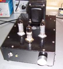
After the chassis is finished, for the sake of beauty, it is painted with black self-spray paint. After the paint film dries out, you can fix the switch, indicator, power socket, and RCA seat, see Figure 3, and then fix the power supply cattle, tube base, electrolytic capacitor clip And the terminal block inside.
First weld the 220V AC power cord and switch. Then solder the rectifier, 6H30, 6P14 filament connection parts.
The filament of 6H30 is 4 and 5 feet, and one of the 4 or 5 feet can be directly grounded. If there is AC noise, you can also try to use two 10 to 20 ohm resistors, soldered to the 4 and 5 pins, and then put The other ends of the two resistors are soldered together and connected to a common ground.
The 6BQ5 filaments are connected in parallel and floating, that is, they are only connected to a set of 6.3V AC, not grounded. After the installation is complete, when the power is tested, measure the cathode voltage of 6BQ5, and use two resistors to divide the voltage, which is slightly higher than the cathode voltage. can.
After welding, first energize to test the voltage (at this time, you should pay attention to handle the high-voltage terminal of the power transformer, you can wrap it with insulating tape first to avoid the risk of electric shock), after normal, you can insert the rectifier, 6P14 and 6H30 tubes , Power-on test, and test the filament voltage again. If the voltages are correct and the tubes are all lit normally, it means that the filament power supply part can already work normally. It needs to be noted that the power consumption of the grid is different between day and night, so The city power will float up and down at 220V, because the filaments are AC power supply, so the fluctuation factor of the city power should be considered when checking the filament voltage.
Fix the high-voltage electrolysis and choke coil, weld the wiring, and check it with the power-on test first, and pay attention to the high-voltage part must be welded and then check the discharge resistance, otherwise, because the chassis is relatively small, it is very difficult to adjust the components inside It is easily hit by the electric charge accumulated by high-voltage electrolysis.
The power supply part is correct, you can then weld the circuit amplification part, the amplification part is very simple, pay attention to the component pins not to be virtual soldered, after welding, plug in the tube and you can preliminary test.
Turn on the power, the tube filament slowly lights up, and then you can test the circuit. During the test, it was found that because the 6H30 tube has a large current, the voltage is simply stabilized by CLC, and the effect cannot meet the requirements. The performance is that the input terminal is short-circuited, and the AC noise voltage at the output terminal is higher. Tested with a DA16 millivoltmeter to reach 20mV. Helpless, the original plan had to give up.
Because the opening of the chassis can not be changed, it is planned to change the original tube rectification to transistor rectification, so that the output voltage can be increased, and the original rectifier position is added to 6N5 as a power adjustment tube. This gourd tube looks very beautiful. The power supply part is changed to be processed on the epoxy board with rivet solder and wire. First draw a sketch on the paper and arrange the location of the components. In order to find the best wiring plan, it took a long time to determine the final plan. Holes were made overnight and the rivets were installed the next day. Prepare the components for welding.
When preparing the components according to the circuit diagram, I just saw Mr. Li's message in Taipei and found that a key problem was ignored. That is, 6N5 is used as a regulator tube to meet the voltage drop of 60 to 90V. Although the output voltage of the transistor rectifier increases, But the final output voltage can only be around 280 ~ 290V, which can not meet the 350V voltage requirement of line amplification. Helpless, the newly-made board has to be abandoned, and now we have to choose transistors, field effect transistors or LM317 as the regulated power supply. In this way, the original tube seat for installing 6N5 was vacated, and two treatment methods were thought of. One is to find a heat sink, cover the hole, and at the same time act as a heat sink for the transistor. The second is to install a large eight-pin voltage amplifier tube, as a voltage amplifier tube for regulated power supply. I remember that there was a previous article in the "Hi-Fi audio" magazine that imitated the 300B, and it also has a soft start function. However, considering the interference of the AC filament, I think that the first method is better, so I restarted the wiring. Arrange parts location. Alas, this 6H30 is really bad service!
The third power board uses the simplified board of the Matisse power supply. The circuit diagram is shown in Figure 4. This circuit has very good performance. I have made more than a dozen pieces for my friends. The AC ripple voltage is only 0.1mV. No wonder Hong Kong and Taiwan enthusiasts It will also be used frequently. Here, the ceiling welding is used. The wiring of the main filtering part is shown in Figure 5, and the main voltage stabilizing part is shown in Figure 6. First fix the MJE13007 and LM317 to the heat sink, pay attention to the installation of insulating gaskets and insulating sheets, install To the case, because there are few components, it is welded quickly.
Turn on the power, the output voltage is 350V, look at the waveform of the power supply voltage, a horizontal straight line, indicating that the regulated power supply works well!
The installation of the internal power board can be seen in Figure 7. The original plan was to use dual choke balanced filtering, but since the voltage drop of a choke at full load is 20V, it is limited by the output voltage, 390V-20V-20V = 350V, unable to meet the input voltage requirements of the regulated power supply, had to change to a single choke.
Measurement of operating point: The voltage at each point is shown in the figure, B + 348V, 6H30 screen voltage to ground 170V, cathode voltage: 9.2V, the calculated screen current Ip = 19.6mA. The basic and design work points coincide.
Ground the input terminal, and then connect an oscilloscope to the output terminal to observe, almost a horizontal line, tested with a DA16 millivolt meter, 5mV, still has some effects. Considering that the output terminal capacitance is open, if the load is connected, the estimated noise voltage is still Will be reduced, so it can be considered that the requirements are basically met. There are many oscilloscopes that can provide a lot of convenience for making a tube amplifier. Sometimes the circuit is high-frequency self-excited, and it is difficult to detect without an oscilloscope. Now the second-hand 20M dual trace is only 3 or 400 yuan, and one should be prepared if possible.
There is also a small episode. I started using the second-hand EH gold foot 6H30 and found that the voltage of the left and right channels of the 6H30 differed by 20V. A new pair of Dawning 6BQ5 was replaced. This is still the case. The new Sovtek brand 6H30 was replaced. The test found that the voltage The difference is less than 2V, it seems that if the requirements are high, the 6H30 tube also needs to be selected and matched.
The working point of the circuit is basically normal. You can make some detailed adjustments to the sound of the pre-stage in the next step. This circuit is relatively simple and can be done by adjusting the working point a little and replacing the output coupling capacitor. For friends who have just come into contact with the amplifier, the 6H30's screen load can also be tested in several forms, such as resistance, inductance, constant current source, etc., to practice hands first, and secondly to increase some perceptual knowledge.
solar &wind hybrid street lighting system have prominent advantages of compact design, energy saving and self-powering. In this system, wind turbine are complemented by solar power in supplying power for Led Lamp, as to its hybrid characteristics, which could provide a balance.It's advantages is that if rainy days,cannot use the sun power,then the wind power can work instead.It applies to the place where wind power is strong.
Solar Wind Hybrid Street Light
Solar Wind Hybrid Street Light,Hybrid Solar Street Light,Wind Solar Street Light
Yangzhou Beyond Solar Energy Co.,Ltd. , https://www.ckbsolar.com