Automotive power ICs cover a wide range of automotive IC applications and functional components. They all have a primary function of supplying, transforming or driving electrical energy from a few milliwatts to several kilowatts. The operating range of these ICs is compatible with the automotive electrical system voltages of 12V, 24V and 48V. Applications range from simple MOSFETs to high-side, low-side and bridge switches with integrated protection and diagnostics, linear power conditioning ICs and switching power supply adjustment ICs, to high integration for safety systems such as ABS and airbags ASIC. Power switches in automotive electronic systems have high side (HSD), low side (LSD) and bridge switches.
This article refers to the address: http://
In the design of the system, whether the high-side switch or the low-side switch is used in the power IC, for the low-side drive, the following details need to be considered:
What is the normal current of the load? What is the maximum current?
Is the load capacitive? If it is capacitive, what is the inrush current?
Is the load inductive? If it is emotional, the energy when it is turned off?
Is the load control mode on/off or PWM? If it is PWM, what is the frequency and duty cycle?
What is the working ambient temperature of the load? What is the limit temperature?
If the system is Ground open, what is the impact on the load?
Is the power IC package required to be SMT or through-hole? If it is SMT, how much area is connected to the heat sink of the power IC? If it is through-hole, what shape of heat sink is used?
Does the load require diagnostics? What diagnostics are needed if needed? Overcurrent, overvoltage, overtemperature or short circuit?
Does the load have the following applications (Reverse battery, Load dump, Over voltage, etc)?
For medium to high side drives in power ICs, the following technical details need to be considered:
What is the normal load current? What is the maximum current?
Is the load capacitive? If it is capacitive, what is the inrush current?
Is the load inductive? If it is emotional, the energy when it is turned off?
Is the load control mode on/off or PWM? If it is PWM, what is the frequency and duty cycle?
What is the working ambient temperature of the load? What is the limit temperature?
Is the power IC package required to be SMT or through-hole? If it is SMT, how much area is connected to the heat sink of the power IC? If it is through-hole, what shape of heat sink is used?
Does the load require diagnostics? What diagnostics are needed if needed? Overcurrent, overvoltage, overtemperature or short circuit?
Does the load have the following applications (Reverse battery, Load dump, Over voltage, etc)?
Here are some comparisons when driving loads with HSD and LSD:
1) On-state resistance
The on-state resistance of the NMOS is smaller than that of the PMOS under the same conditions. This is because the conduction speed of electrons is faster than that of holes, thus affecting the on-state resistance. Also because in order to pursue low on-state resistance, in some high-side drive applications, the PMOS is used as a high-side application with a charge pump plus NMOS. The price is high, and the drive circuit is more complicated than LSD.
2) Sampling circuit
For HSD protection, if current sampling is required, a differential configuration is required to achieve current sampling; for LSD, a single-ended configuration is sufficient. In this sense, LSD has a cost advantage over HSD because the cost of using differential circuits is higher than the cost of using single-ended.
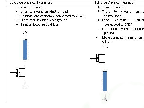
3) Wire system requirements
Since most of the current cars are negative ground, there are a number of benefits to using HSD to power the load. If one end of the load is directly connected to the ground of the chassis, only one wire is needed to power the load, which saves the cost of the system.
4) The impact of failure on the system
This is based on the requirements of the system, which type of load to choose. In the aircraft's load failure type, if the load fails, the safest way is to let the load continue to run; for the load application of the car, the opposite is true. For example, in the engine management control unit, the switch that controls the oil pump is HSD. This is because in most cases, when the drive module fails, the oil pump is turned off. This design is very advantageous for a car accident or system failure.
The table below gives a comprehensive comparison of HSD and LSD:
In summary, whether using LSD or HSD, there are advantages and disadvantages. In the end, the driver of that type is chosen in the automotive electronic module, in which occasions to apply, the type of diagnosis, the danger caused by the failure, and comprehensive consideration can make a compromise choice.
Fiber Optic Cabinet is designed for a cross connection between telecom feeder cable and customer cable. It is normally in a floor-standing or occasionally wall-mounted way to be placed over the street serving as one of the optical nodes in access network. Fiber optic cross connect cabinet is typically used in buildings to splice incoming Outside Plant (OSP) fiber optical cables into customer premises cables. In certain situations, the Telecommunication Cabinet is necessary to mount it on the exterior of a building or a telecommunication pole.
Fiber Distribution Cabinet needs to be easily accessible and manageable in size. The dimension could be customized by client. If necessary, the box can be locked to keep the splices secure.Foclink,a reliable supplier of fiber optic cabinet,is always beside u 7*24
Fiber Optic Cabinet
Fiber Optic Cabinet,Telecommunication Cabinet,Fiber Cross Connect Cabinet,Fiber Distribution Cabinet
Foclink Co., Ltd , http://www.scfiberpigtail.com