Abstract: This application note describes how to adjust the pulse waveforms of the DS3151, DS3152, DS3153, and DS3154. Although the signal pulses of the DS315x always meet the specifications, sometimes the pulse shape is not exactly what the customer wants. This application note describes how to adjust the pulse width and amplitude in T3, E3, and STS-1 modes, and how to adjust the pulse waveform in T3 and STS-1 modes. All of these can be achieved by changing the value of the internal test register. The oscilloscope waveforms illustrated in this application note were obtained by testing with the DS3154DK design kit.
Introduction This application note describes how to adjust the pulse waveforms of the DS3151, DS3152, DS3153, and DS3154 (DS315x). Although the signal pulses of the DS315x always meet the specifications, sometimes the pulse shape is not exactly what the customer wants. This application note describes how to adjust the pulse width and amplitude in T3, E3, and STS-1 modes, and how to adjust the pulse waveform in T3 and STS-1 modes. All of these can be achieved by changing the value of the internal test register. The oscilloscope waveforms illustrated in this application note were obtained by testing with the DS3154DK design kit.
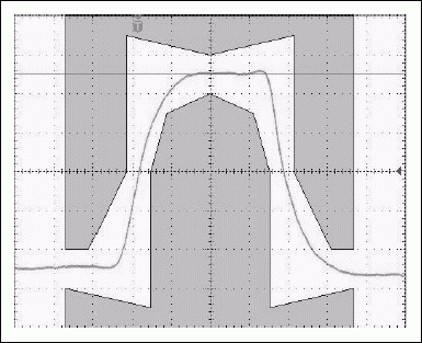
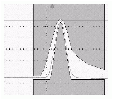
Figure 1. Typical E3 and T3 transmit pulses
Figure 1 shows the transmit pulse waveforms in E3 and T3 modes without using the test register. In E3, T3 or STS-1 mode, the pulse width and amplitude can be adjusted by changing the value of the test register. The address of these test registers is, 0Ah corresponds to the line interface unit (LIU) port 1, 1Ah corresponds to the LIU port 2, 2Ah corresponds to LIU port 3, 3Ah corresponds to LIU port 4.
In E3, T3 or STS-1 mode to adjust the width of the transmitted pulse LIU can use 11-stage delay-locked loop (DLL) circuit or 12-stage DLL circuit. The more stages in the DLL, the narrower the pulse width, and vice versa. Set the registers at addresses 0Ah, 1Ah, 2Ah, and 3Ah (corresponding to LIU ports 1, 2, 3, and 4 respectively) to 01h, and LIU will use an 11-level DLL circuit. Set the test registers at addresses 0Ah, 1Ah, 2Ah, and 3Ah to 02h, and LIU will use a 12-level DLL circuit.
By default, the LIU in E3 mode uses an 11-level DLL, and TLBO is ignored. In T3 and STS-1 modes, LIU uses 11-level DLL when TLBO = 1, and 12-level DLL when TLBO = 0.
In E3 mode, if we want to reduce the pulse width, we can set the 0Ah, 1Ah, 2Ah and 3Ah registers (corresponding to LIU ports 1, 2, 3 and 4) to 02h, forcing LIU to work in 12-level DLL. Figure 2 shows the transition of the E3 pulse from a typical pulse waveform to a narrower pulse waveform.
In T3 and STS-1 modes, when TLBO = 0, LIU uses a 12-level DLL. In order to increase the pulse width, we can set the value of 0Ah, 1Ah, 2Ah and 3Ah registers (corresponding to LIU ports 1, 2, 3 and 4 respectively) to 01h, forcing LIU to work in 11-level DLL. Figure 3 shows the transition of the T3 pulse width from a typical value to a wider pulse.
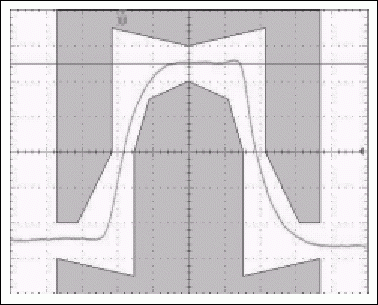
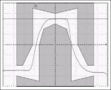
Figure 2. Typical E3 pulse and narrower E3 pulse with 12-level DLL
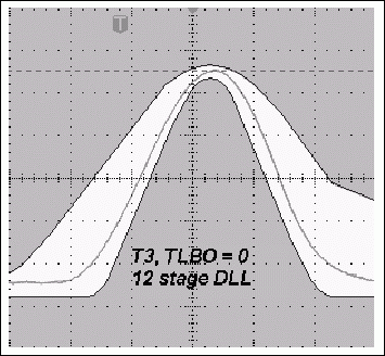
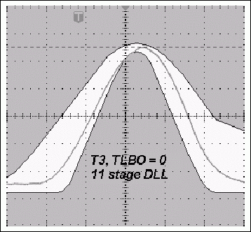
Figure 3. Typical T3 pulse with 12-level DLL and wider T3 pulse with 11-level DLL when TLBO = 0
Similarly, in T3 and STS-1 modes, when TLBO = 1, LIU uses 11-level DLL. In order to reduce the pulse width, we can set the value of 0Ah, 1Ah, 2Ah and 3Ah registers (corresponding to LIU ports 1, 2, 3 and 4 respectively) to 02h, forcing LIU to work in 12-level DLL. Figure 4 shows the transition of the T3 pulse width from a typical value to a narrower pulse.
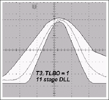
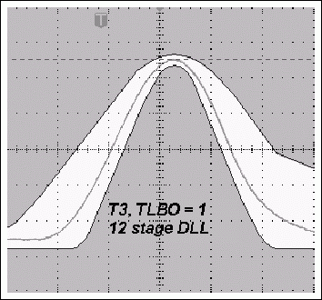
Figure 4. Typical T3 pulse with 11-level DLL and narrower T3 pulse with 12-level DLL when TLBO = 1.
Adjust the amplitude of the transmitted pulse in E3, T3 or STS-1 mode. By setting the value of the test registers at 0Ah, 1Ah, 2Ah and 3Ah in DS315x, we can increase or decrease the transmission in E3, T3 and STS-1 mode The amplitude of the pulse. When the register addresses 0Ah, 1Ah, 2Ah and 3Ah are set to 08h, the amplitude of the corresponding LIU ports 1, 2, 3 and 4 will increase by 2%. Figure 5 shows the E3 pulse before and after the amplitude increases by 2%.
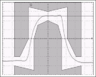
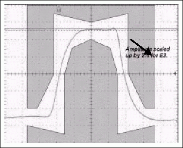
Figure 5. Typical E3 pulse and pulse with amplitude increased by 2% (test register set to 08h)
When the values ​​of the test register addresses 0Ah, 1Ah, 2Ah, and 3Ah are set to 10h, the amplitude of the corresponding LIU ports 1, 2, 3, and 4 will increase by 4%. Figure 6 shows the E3 pulse before and after an increase in amplitude of 4%.
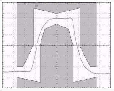
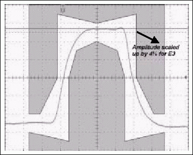
Figure 6. Typical E3 pulses and pulses with an amplitude increase of 4% (test register set to 10h)
When the values ​​of the test register addresses 0Ah, 1Ah, 2Ah and 3Ah are set to 20h, the amplitude of the corresponding LIU ports 1, 2, 3 and 4 will increase by 8%. Figure 7 shows the E3 pulse before and after the amplitude increases by 8%.
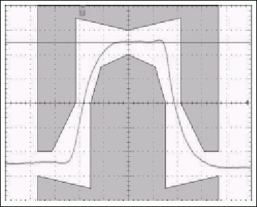
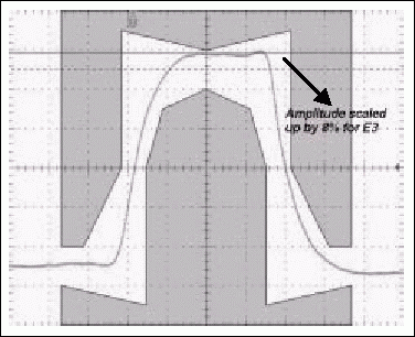
Figure 7. Typical E3 pulses and pulses with an amplitude increase of 8% (test register set to 20h)
When the values ​​of the test register addresses 0Ah, 1Ah, 2Ah, and 3Ah are set to 40h, the amplitude of the corresponding LIU ports 1, 2, 3, and 4 will be reduced by 8%. Figure 8 shows the E3 pulse before and after the amplitude is reduced by 8%.
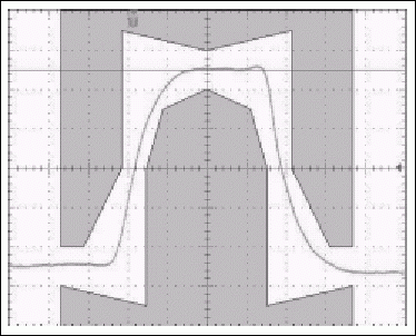
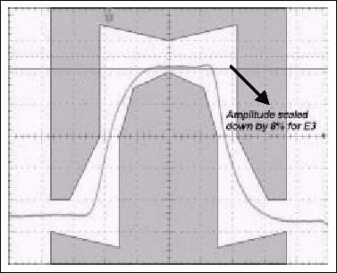
Figure 8. Typical E3 pulses and pulses with amplitude reduced by 8% (test register set to 40h)
A value of 10h increases the amplitude of LIU by 4%, and a value of 20h increases the amplitude of LIU by 8%. The 30h (10h + 20h) after the two are added together will increase the pulse amplitude of LIU by 12%. Selecting 50h (10h + 40h) will reduce the amplitude by 4%. Figure 9 shows the E3 pulse before and after the amplitude is reduced by 4%. It is not recommended to use the value of 60h because it will increase in magnitude until the current limiter is triggered.
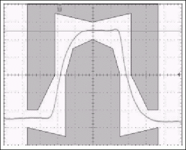
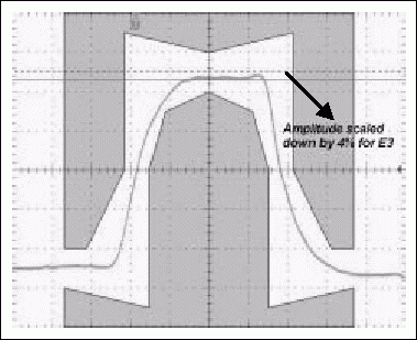
Figure 9. Typical E3 pulse and pulse with amplitude reduced by 4% (test register set to 50h)
Adjust the timing of the transmitted waveform in T3 or STS-1 mode In T3 or STS-1 mode, the timing of the transmitted waveform can be adjusted by changing the value of the test register. The address of these test registers is, 0Bh corresponds to LIU port 1, 1Bh Corresponds to LIU port 2, 2Bh corresponds to LIU port 3, and 3Bh corresponds to LIU port 4. Figure 10 shows a typical T3 pulse. In order to explain the effect of data changes in the register 0 address on the port 1 0Bh, LIU port 2 address 1Bh, LIU port 3 address 3Bh, LIU port 4 address 3Bh on the T3 or STS-1 pulse, we divide the T3 pulse into 12 segments.
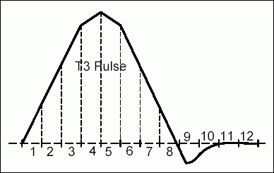
Figure 10. Typical T3 pulse divided into 12 segments
When the register addresses 0Bh, 1Bh, 2Bh, and 3Bh are set to 01h, the width of the third segment will increase by 350ps. This increases the total width of segments 1 to 4 by 350ps. The pulse amplitude also increases at the same time. The amount of undershoot in the 9th and 10th sections of the pulse is also reduced. Figure 11 shows a typical T3 pulse and the change in the pulse after writing 01h to the test registers at addresses 0Bh, 1Bh, 2Bh, and 3Bh.
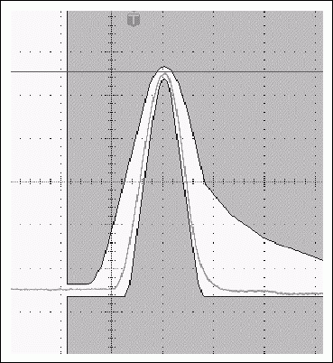
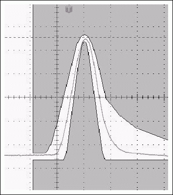
Figure 11. Typical T3 pulse and its change in the same pulse when setting the test register to 01h
When the values ​​of register addresses 0Bh, 1Bh, 2Bh, and 3Bh are set to 81h, the second and third segments are widened by 350 ps, ​​respectively. This increases the total width of segments 1 to 4 by 700 ps. The pulse amplitude also increases at the same time. The amount of undershoot in the 9th and 10th sections of the pulse is also smaller than when we set the register to 01h. Figure 12 shows a typical T3 pulse and the pulse change after writing 81h to the test registers at addresses 0Bh, 1Bh, 2Bh, and 3Bh.
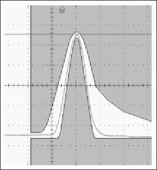
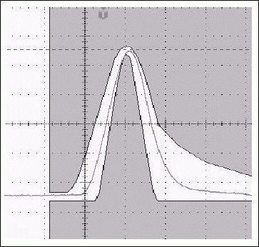
Figure 12. Typical T3 pulse and its change in the same pulse when setting the test register to 81h
When the register addresses 0Bh, 1Bh, 2Bh, and 3Bh are set to 02h, the width of the fourth segment will increase by 350ps. This increases the total width of segments 1 to 4 by 350ps. The pulse amplitude does not increase. The undershoot in paragraphs 9 and 10 is reduced, but the amount of decrease is not as large as when we set the register value to 01h. Figure 13 shows a typical T3 pulse and the pulse change after writing 02h to the test registers at addresses 0Bh, 1Bh, 2Bh, and 3Bh.
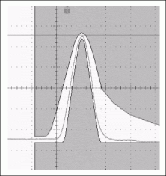
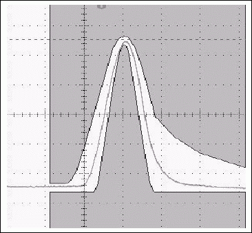
Figure 13. Typical T3 pulse and its change in the same pulse when setting the test register to 02h
When the values ​​of register addresses 0Bh, 1Bh, 2Bh, and 3Bh are set to 04h, the width of the fifth segment is increased by 350 ps. This increases the total width of the 5 to 8 segments by 350ps. The pulse amplitude did not decrease. The undershoot in paragraphs 9 and 10 has increased. Figure 14 shows a typical T3 pulse, and the pulse change after writing 04h to the test registers at addresses 0Bh, 1Bh, 2Bh, and 3Bh.

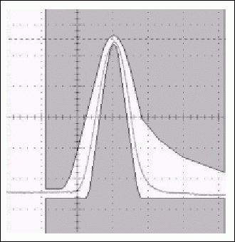
Figure 14. Typical T3 pulse and its change in the same pulse when setting the test register to 04h
When the values ​​of the register addresses 0Bh, 1Bh, 2Bh, and 3Bh are set to 08h, the width of the seventh segment is increased by 350 ps. This increases the total width of the 5 to 8 segments by 350ps. The pulse amplitude is slightly reduced. The undershoot in paragraphs 9 and 10 is more than when the register is 04h. Figure 15 shows a typical T3 pulse and how the pulse changes after writing 08h to the test registers at addresses 0Bh, 1Bh, 2Bh, and 3Bh.
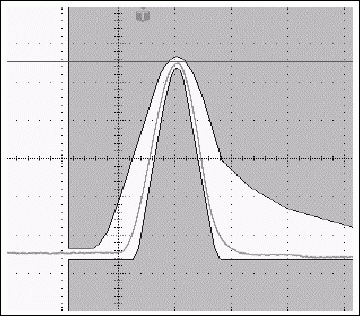
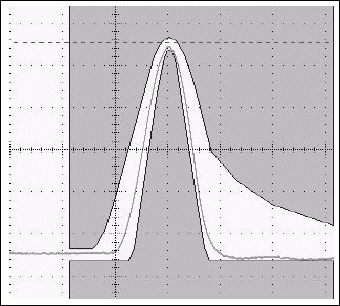
Figure 15. Typical T3 pulse and its change in the same pulse when setting the test register to 08h
When the values ​​of the register addresses 0Bh, 1Bh, 2Bh, and 3Bh are set to 88h, the width of the sixth and seventh segments increases by 350 ps each. This increases the total width of the 5 to 8 segments by 700 ps. The pulse amplitude has also decreased. The amount of undershoot in paragraphs 9 and 10 is more increased than when the register is set to 08h. Figure 16 shows a typical T3 pulse and how the pulse changes after writing 88h to the test registers at addresses 0Bh, 1Bh, 2Bh, and 3Bh.

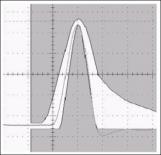
Figure 16. Typical T3 pulse and its change in the same pulse when setting the test register to 88h. How to adjust the pulse waveform, the width or amplitude of the pulse depends on the actual pulse shape the user gets on their circuit board.
Introduction This application note describes how to adjust the pulse waveforms of the DS3151, DS3152, DS3153, and DS3154 (DS315x). Although the signal pulses of the DS315x always meet the specifications, sometimes the pulse shape is not exactly what the customer wants. This application note describes how to adjust the pulse width and amplitude in T3, E3, and STS-1 modes, and how to adjust the pulse waveform in T3 and STS-1 modes. All of these can be achieved by changing the value of the internal test register. The oscilloscope waveforms illustrated in this application note were obtained by testing with the DS3154DK design kit.
Figure 1. Typical E3 and T3 transmit pulses
Figure 1 shows the transmit pulse waveforms in E3 and T3 modes without using the test register. In E3, T3 or STS-1 mode, the pulse width and amplitude can be adjusted by changing the value of the test register. The address of these test registers is, 0Ah corresponds to the line interface unit (LIU) port 1, 1Ah corresponds to the LIU port 2, 2Ah corresponds to LIU port 3, 3Ah corresponds to LIU port 4.
In E3, T3 or STS-1 mode to adjust the width of the transmitted pulse LIU can use 11-stage delay-locked loop (DLL) circuit or 12-stage DLL circuit. The more stages in the DLL, the narrower the pulse width, and vice versa. Set the registers at addresses 0Ah, 1Ah, 2Ah, and 3Ah (corresponding to LIU ports 1, 2, 3, and 4 respectively) to 01h, and LIU will use an 11-level DLL circuit. Set the test registers at addresses 0Ah, 1Ah, 2Ah, and 3Ah to 02h, and LIU will use a 12-level DLL circuit.
By default, the LIU in E3 mode uses an 11-level DLL, and TLBO is ignored. In T3 and STS-1 modes, LIU uses 11-level DLL when TLBO = 1, and 12-level DLL when TLBO = 0.
In E3 mode, if we want to reduce the pulse width, we can set the 0Ah, 1Ah, 2Ah and 3Ah registers (corresponding to LIU ports 1, 2, 3 and 4) to 02h, forcing LIU to work in 12-level DLL. Figure 2 shows the transition of the E3 pulse from a typical pulse waveform to a narrower pulse waveform.
In T3 and STS-1 modes, when TLBO = 0, LIU uses a 12-level DLL. In order to increase the pulse width, we can set the value of 0Ah, 1Ah, 2Ah and 3Ah registers (corresponding to LIU ports 1, 2, 3 and 4 respectively) to 01h, forcing LIU to work in 11-level DLL. Figure 3 shows the transition of the T3 pulse width from a typical value to a wider pulse.
Figure 2. Typical E3 pulse and narrower E3 pulse with 12-level DLL
Figure 3. Typical T3 pulse with 12-level DLL and wider T3 pulse with 11-level DLL when TLBO = 0
Similarly, in T3 and STS-1 modes, when TLBO = 1, LIU uses 11-level DLL. In order to reduce the pulse width, we can set the value of 0Ah, 1Ah, 2Ah and 3Ah registers (corresponding to LIU ports 1, 2, 3 and 4 respectively) to 02h, forcing LIU to work in 12-level DLL. Figure 4 shows the transition of the T3 pulse width from a typical value to a narrower pulse.
Figure 4. Typical T3 pulse with 11-level DLL and narrower T3 pulse with 12-level DLL when TLBO = 1.
Adjust the amplitude of the transmitted pulse in E3, T3 or STS-1 mode. By setting the value of the test registers at 0Ah, 1Ah, 2Ah and 3Ah in DS315x, we can increase or decrease the transmission in E3, T3 and STS-1 mode The amplitude of the pulse. When the register addresses 0Ah, 1Ah, 2Ah and 3Ah are set to 08h, the amplitude of the corresponding LIU ports 1, 2, 3 and 4 will increase by 2%. Figure 5 shows the E3 pulse before and after the amplitude increases by 2%.
Figure 5. Typical E3 pulse and pulse with amplitude increased by 2% (test register set to 08h)
When the values ​​of the test register addresses 0Ah, 1Ah, 2Ah, and 3Ah are set to 10h, the amplitude of the corresponding LIU ports 1, 2, 3, and 4 will increase by 4%. Figure 6 shows the E3 pulse before and after an increase in amplitude of 4%.
Figure 6. Typical E3 pulses and pulses with an amplitude increase of 4% (test register set to 10h)
When the values ​​of the test register addresses 0Ah, 1Ah, 2Ah and 3Ah are set to 20h, the amplitude of the corresponding LIU ports 1, 2, 3 and 4 will increase by 8%. Figure 7 shows the E3 pulse before and after the amplitude increases by 8%.
Figure 7. Typical E3 pulses and pulses with an amplitude increase of 8% (test register set to 20h)
When the values ​​of the test register addresses 0Ah, 1Ah, 2Ah, and 3Ah are set to 40h, the amplitude of the corresponding LIU ports 1, 2, 3, and 4 will be reduced by 8%. Figure 8 shows the E3 pulse before and after the amplitude is reduced by 8%.
Figure 8. Typical E3 pulses and pulses with amplitude reduced by 8% (test register set to 40h)
A value of 10h increases the amplitude of LIU by 4%, and a value of 20h increases the amplitude of LIU by 8%. The 30h (10h + 20h) after the two are added together will increase the pulse amplitude of LIU by 12%. Selecting 50h (10h + 40h) will reduce the amplitude by 4%. Figure 9 shows the E3 pulse before and after the amplitude is reduced by 4%. It is not recommended to use the value of 60h because it will increase in magnitude until the current limiter is triggered.
Figure 9. Typical E3 pulse and pulse with amplitude reduced by 4% (test register set to 50h)
Adjust the timing of the transmitted waveform in T3 or STS-1 mode In T3 or STS-1 mode, the timing of the transmitted waveform can be adjusted by changing the value of the test register. The address of these test registers is, 0Bh corresponds to LIU port 1, 1Bh Corresponds to LIU port 2, 2Bh corresponds to LIU port 3, and 3Bh corresponds to LIU port 4. Figure 10 shows a typical T3 pulse. In order to explain the effect of data changes in the register 0 address on the port 1 0Bh, LIU port 2 address 1Bh, LIU port 3 address 3Bh, LIU port 4 address 3Bh on the T3 or STS-1 pulse, we divide the T3 pulse into 12 segments.
Figure 10. Typical T3 pulse divided into 12 segments
When the register addresses 0Bh, 1Bh, 2Bh, and 3Bh are set to 01h, the width of the third segment will increase by 350ps. This increases the total width of segments 1 to 4 by 350ps. The pulse amplitude also increases at the same time. The amount of undershoot in the 9th and 10th sections of the pulse is also reduced. Figure 11 shows a typical T3 pulse and the change in the pulse after writing 01h to the test registers at addresses 0Bh, 1Bh, 2Bh, and 3Bh.
Figure 11. Typical T3 pulse and its change in the same pulse when setting the test register to 01h
When the values ​​of register addresses 0Bh, 1Bh, 2Bh, and 3Bh are set to 81h, the second and third segments are widened by 350 ps, ​​respectively. This increases the total width of segments 1 to 4 by 700 ps. The pulse amplitude also increases at the same time. The amount of undershoot in the 9th and 10th sections of the pulse is also smaller than when we set the register to 01h. Figure 12 shows a typical T3 pulse and the pulse change after writing 81h to the test registers at addresses 0Bh, 1Bh, 2Bh, and 3Bh.
Figure 12. Typical T3 pulse and its change in the same pulse when setting the test register to 81h
When the register addresses 0Bh, 1Bh, 2Bh, and 3Bh are set to 02h, the width of the fourth segment will increase by 350ps. This increases the total width of segments 1 to 4 by 350ps. The pulse amplitude does not increase. The undershoot in paragraphs 9 and 10 is reduced, but the amount of decrease is not as large as when we set the register value to 01h. Figure 13 shows a typical T3 pulse and the pulse change after writing 02h to the test registers at addresses 0Bh, 1Bh, 2Bh, and 3Bh.
Figure 13. Typical T3 pulse and its change in the same pulse when setting the test register to 02h
When the values ​​of register addresses 0Bh, 1Bh, 2Bh, and 3Bh are set to 04h, the width of the fifth segment is increased by 350 ps. This increases the total width of the 5 to 8 segments by 350ps. The pulse amplitude did not decrease. The undershoot in paragraphs 9 and 10 has increased. Figure 14 shows a typical T3 pulse, and the pulse change after writing 04h to the test registers at addresses 0Bh, 1Bh, 2Bh, and 3Bh.
Figure 14. Typical T3 pulse and its change in the same pulse when setting the test register to 04h
When the values ​​of the register addresses 0Bh, 1Bh, 2Bh, and 3Bh are set to 08h, the width of the seventh segment is increased by 350 ps. This increases the total width of the 5 to 8 segments by 350ps. The pulse amplitude is slightly reduced. The undershoot in paragraphs 9 and 10 is more than when the register is 04h. Figure 15 shows a typical T3 pulse and how the pulse changes after writing 08h to the test registers at addresses 0Bh, 1Bh, 2Bh, and 3Bh.
Figure 15. Typical T3 pulse and its change in the same pulse when setting the test register to 08h
When the values ​​of the register addresses 0Bh, 1Bh, 2Bh, and 3Bh are set to 88h, the width of the sixth and seventh segments increases by 350 ps each. This increases the total width of the 5 to 8 segments by 700 ps. The pulse amplitude has also decreased. The amount of undershoot in paragraphs 9 and 10 is more increased than when the register is set to 08h. Figure 16 shows a typical T3 pulse and how the pulse changes after writing 88h to the test registers at addresses 0Bh, 1Bh, 2Bh, and 3Bh.
Figure 16. Typical T3 pulse and its change in the same pulse when setting the test register to 88h. How to adjust the pulse waveform, the width or amplitude of the pulse depends on the actual pulse shape the user gets on their circuit board.
Philippines Power Plug,Philippines Power Outlet,Philippines Electrical Outlet,Philippines Electric Socket
Heikki Technology Co., Ltd. , https://www.heikkipower.com