A signal generator is a device that provides electrical signals at a variety of frequencies, waveforms, and output levels. Used as a signal source or excitation source for testing when measuring the amplitude characteristics, frequency characteristics, transmission characteristics, and other electrical parameters of various telecommunication systems or telecommunication devices, as well as measuring the characteristics and parameters of components.
Signal generators, also known as signal sources or oscillators, have a wide range of applications in production practice and technology. Various waveform curves can be represented by trigonometric equations. A circuit capable of generating a variety of waveforms such as a triangular wave, a sawtooth wave, a rectangular wave (including a square wave), and a sine wave is called a function signal generator.
The signal source is the basic electronic equipment in the fields of measurement and debugging of electronic products and technical support for military equipment. With the development of science and technology and the advancement of measurement technology, ordinary signal generators have been unable to meet the needs of production debugging in the field of electronic technology. DDS technology is an emerging direct digital frequency synthesis technology with high frequency resolution, fast frequency switching, continuous switching phase, low phase noise of output signal, programmable, all-digital easy integration, small size and light weight. Therefore, it has broad application prospects in the fields of radar and communication.
1 system designThe design scheme of the full digital-controlled function signal generator using DDS as the signal generation core device proposed in this paper can be set according to the output signal waveform type, the output signal amplitude and frequency can be numerically controlled, the output frequency is wide, etc., and the American A/D company is selected. The AD9850 chip controls and processes the 32-bit frequency control word of the AD9850 through a single-chip program, and then amplifies it to a digital attenuation network with a digital potentiometer as the core, thereby realizing the full range of signal amplitude, frequency, type, and output options. digital control. The structure of the function signal generator is shown in Figure 1.
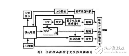
The system is mainly composed of a single chip, a DDS direct frequency signal synthesizer, a digital attenuation circuit, a true RMS conversion module, an A/D conversion module, and a digital integral selection circuit.
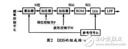
2 The basic principles of DDSThe Direct Digital Synthesizer is a frequency synthesis technique that directly synthesizes the desired waveform from the phase concept. A direct digital synthesizer typically consists of a phase accumulator, adder, waveform storage ROM, D/A converter, and low pass filter (LPF). The composition of the DDS is shown in Figure 2. Where K is the frequency control word (also called phase increment), P is the phase control word, W is the waveform control word, fc is the reference clock frequency, N is the word length of the phase accumulator, D is the ROM data bit and D/ The word length of the A converter. The phase accumulator is accumulated by the step length K under the control of the clock fc, and the output N-bit binary code is added to the phase control word P and the waveform control word W to address the waveform ROM as the address of the waveform ROM, and the waveform ROM output is output. The D-bit amplitude code S(n) is converted into a staircase wave S(t) by D/A conversion, and then smoothed by a low-pass filter to obtain a synthesized signal waveform. Since the synthesized signal waveform depends on the amplitude code stored in the waveform ROM, an arbitrary waveform can be synthesized using DDS.
3.1 DDS signal generation circuit
Considering that DDS has the advantages of high frequency resolution, fast frequency switching, continuous switching phase, low phase noise of output signal, programmable, fully digital, easy to integrate, small size, light weight, etc., the program uses American A/D company. The AD9850 chip uses a single-chip microcomputer as the core control device to transmit the frequency control word to the DDS, so that the DDS outputs the corresponding frequency and type of signals, and the DDS signal generating circuit thereof is shown in FIG.
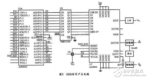
The interface between the MCU and the AD9850 can be either parallel or serial. In order to give full play to the high-speed performance of the chip and save the microcontroller resources, this design chooses the parallel mode to extend the P0 port of the AT89S52 to the parallel input control terminal (D0~D7) of the DDS via the 74HC373 latch. The AD9850 is connected to an active crystal of 120 MHz. The generated sinusoidal signal is removed from the high-frequency harmonics by a low-pass filter (LPF) to obtain a good analog signal. In this way, after the output signal of the D/A converter is low-pass filtered, it is connected to the high-speed comparator inside the AD9850, and a square wave with little jitter can be directly output. Then add the square wave signal to the integration circuit to obtain the triangular wave signal. In addition, the output signal of the arbitrary waveform can also be edited through the keyboard.
3.2 keyboard input interface and LCD interface circuit
The digital input setting circuit in this system uses 2&TImes; 8 matrix keyboard. Because the LCD has many display contents, simple circuit structure, and less occupation of single-chip resources, the system uses RT1602C LCD liquid crystal display to display the type of signal, frequency and peak-to-peak value of sine wave. Figure 4 shows the keyboard input. And LCD interface circuit diagram.
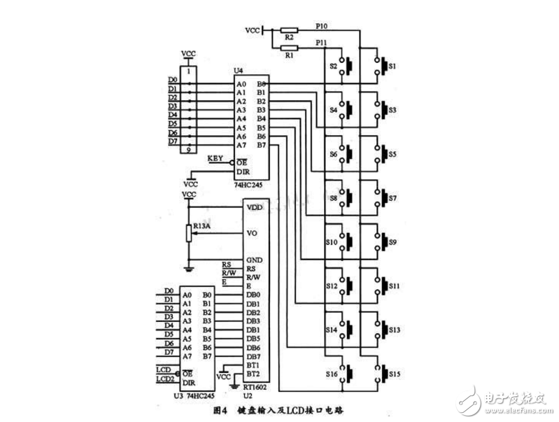
Similarly, considering the IO pin resources of the AT89S52 microcontroller is limited, the keyboard input and LCD output of the system are connected to the P0 port of the AT89S52 microcontroller through the 74HC245, thereby realizing port expansion and multiplexing.
3.3 signal amplitude digital preset circuit
In order to realize the digital control and preset of the output sinusoidal analog signal amplitude, the system uses AD811 high-speed op amp, digital potentiometer attenuation, true RMS conversion, and A/D conversion circuits. The specific circuit diagram is shown in Figure 5. .
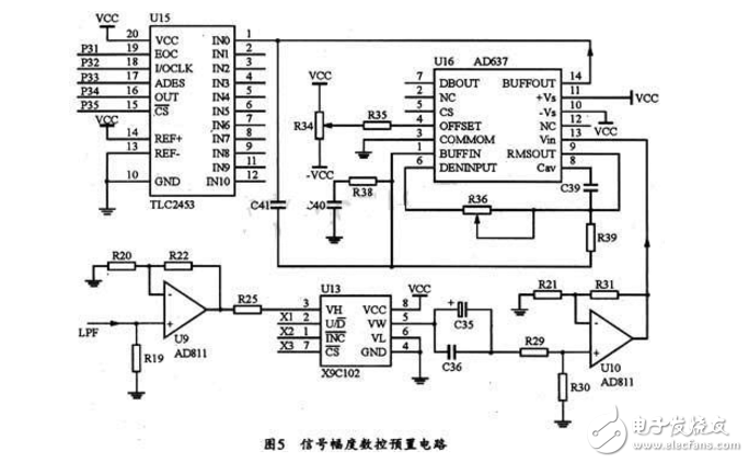
The digital potentiometer X9C102 is a key device for digitally adjustable signal amplitude. The true RMS conversion module AD637 is mainly responsible for the TRMS/DC conversion of the signal, and then sends a digital quantity proportional to the amplitude of the sine wave signal to the MCU through the TLC2453 analog-to-digital conversion, so that the MCU outputs the appropriate amplitude control command.
3.4 integral capacitance automatic switching control circuit
The triangular wave is one of the commonly used signals. The system uses an RC integration circuit to convert the square wave signal into a triangular wave. Due to the wide signal frequency (low frequency up to 1 Hz and high frequency above 60 MHz), different integration capacitors are required to achieve linear integration in different frequency bands (10pF, 100pF, 1 nF, 10nF, 100nF, 1 μF, 10 μF) , 100μF). Based on the needs of numerical control and automatic switching, the system uses the CD4051 eight-choice circuit as shown in Figure 6.
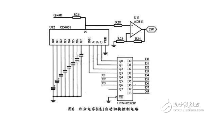
The CD4051's eight-choice control signal is derived from the P0-P3 interface of the AT89S52. The 74HC373P is also set to consider multiplexing the P0 port. After the square wave outputted by the AD9850 is converted into a triangular wave by the integration circuit, the AD811 high-speed operational amplifier can improve its load capacity.
4 system software design4.1 Main program
The main program can control the whole system, including sub-programs such as initialization, display, calculation, keyboard scanning, frequency control and amplitude control of the control system. The main program flow is shown in Figure 7.
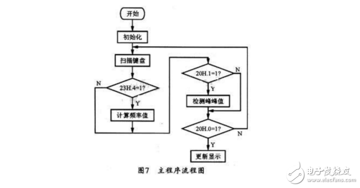
Initialization can set the system to the default working state, and then scan the keyboard to determine whether there is a button press to determine the task to be performed by the user, and at the same time determine by the function flags of 23H.4, 20H.1, and 20H.0. The function that should be completed. When 23H.4=1, the calculated frequency value system works in the frequency meter mode; when 20H.1=1, the detection peak-to-peak system will detect the peak-to-peak value of the output signal: when 20H.0=1. Then update the LCD display content, and when it is finished, return to the keyboard scanner and cycle through it. Each function flag is controlled by a keyboard, peak-to-peak detection, and timing program to implement various functions.
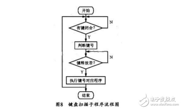
4.2 keyboard scanning subroutine
The keyboard scanning subroutine is shown in Figure 8. Because there are more buttons. This system uses 2 & TImes; 8 determinant keyboard to save I / O port, and use the program to pull all 8 column lines low, then determine whether the two line lines have a low level, if not, indicating that no buttons are pressed, the system Then exit the keyboard scanning program, otherwise, pull down the column line in turn, and then judge whether the line line has low level and judge the key number in turn, and then the key number is determined and then go to the function program corresponding to the key number to execute. The keyboard is mainly convenient for users to set the frequency, amplitude, and work mode.
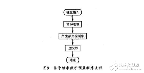
4.3 Signal frequency digital preset subroutine
The digital control program flow of the signal frequency is shown in Figure 9. This part of the program is mainly used to convert the keyboard input value into hexadecimal data, and then generate the corresponding frequency control word and send it to the DDS chip to change the phase increment of the DDS, and finally output the corresponding frequency signal.
Through rigorous experimental tests, the system can fully realize the selection of output signal type, digital preset of signal frequency, digital step adjustment of signal amplitude, etc., which is a kind of output signal with wide frequency coverage (0.023 Hz~40). MHz), high signal resolution, small waveform distortion, full CNC function signal generator. Has a certain practical development value.
Network Accessories,Wifi Adapter,Fiber Optic Network Components,Splitter Fiber Optic
Cixi Dani Plastic Products Co.,Ltd , https://www.dani-fiber-optic.com