1. BD6389 control and implementation method
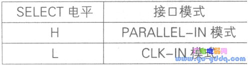
The BD6389 differs from other ICs in that the motor input interface has PARALLEL-IN mode and CLK-IN mode. These two interface control modes can be selected by setting the level of the SELECT pin. As shown in the table below.
1.1PARALLEL-IN mode control
The PARALLEL-IN mode is the same as most stepper motor control chips, as long as the appropriate timing is entered in the corresponding discipline to achieve motor rotation control. For example, if the excitation mode is used to control the rotation of the motor in the whole step, if the corresponding level signals are given to the relevant pins MODEO, MODE1, CW-CCW, and ENABLE, the whole step control and current output waveforms of the BD6398 are as shown in the following figure. Show.
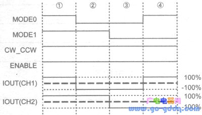
In the above figure, IOUT is the phase current waveform. In the whole step control mode, the drive current amplitude of each step output is 100% output. In PARALLEL-IN mode, the excitation mode supported by the BD6389 chip hardware is divided into two steps: full step and half step. If the DAC is applied and the VREF1 and VREF2 reference voltages are controlled at the same time, higher subdivision control such as 1/4 step, 1/8 step or sine wave input can be realized.
1.2CLK-IN mode control
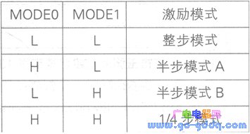
When the BD6389 is operating in CLK-IN mode, its control timing is simpler than in PARALLEL-IN mode. Simply input the clock signal to the CLK pin and level match the other related pins to achieve positive /Reverse control, speed control, excitation mode selection, etc. For the level configuration of MODEO and MODE1, different excitation modes can be selected, as shown in the following table.
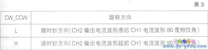
The CW-CCW pin is used for the selection of the direction of rotation as shown in the table below.
Similarly, to achieve the excitation mode for the whole step of controlling the motor rotation as an example, before inputting the CLK pin clock, the following control port levels are configured as follows: MODEO=L, MODE1=L, CW-CCW=L, ENABLE=H SELECT=L, that is, there is no need to input pulses to MODEO, MODE1, CW-CCW, etc., only need to fix the level; then input the PS=H, CLK pin into the clock signal as shown in the figure below, then go to the stepper motor The waveform of the pin interface is as shown in OUTIA, OUTIB, OUT2A, and OUT2B in the figure below, and the whole step control is automatically realized. The clock frequency on the CLK pin determines the rate of rotation of the motor. The higher the frequency, the faster the speed.
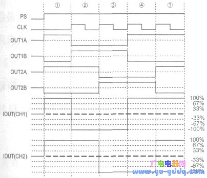
In CLK-IN mode, BD6389 supports four steps of full-step, half-step A, half-step B, and 1/4-step excitation modes. Compared with PARALLEL-IN mode, there are two excitation modes, but at the same time in CLK-IN mode. BD6389 does not support additional microstep control.
Like the BD6384, the BD6389 current decay mode also supports fast, slow, and mixed three attenuation modes. Under normal circumstances, the BD6389 can be operated in mixed attenuation mode. It can also select the appropriate output waveform by observing the output current waveform according to the application. Attenuation mode.
2. BD6389 typical application circuit
The peripheral circuit of BD6389 is relatively simple. As shown in the figure below, the RC circuit connected to the CR1 and CR2 pins is used to generate the PWM oscillation waveform. The R and C parameter values ​​are not recommended to be modified.
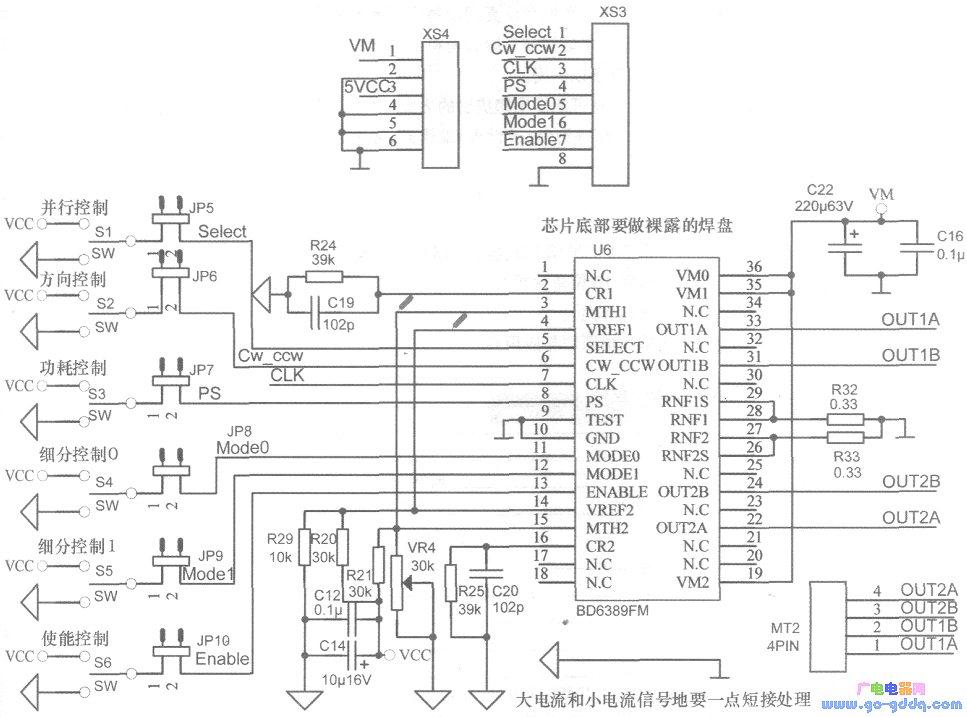
When the complex microstep control is not performed, the two reference voltage pins of VREF1 and VREF2 of BD6389 can be connected together, and the fixed reference voltage is input through the resistor divider, and the reference voltage should not be too large, and the range is 0~2. OV. If the reference voltage exceeds this range, the output current will not change according to the set rules, which may cause chip damage or malfunction. Therefore, the range of the reference voltage must be noted in the application.
In addition to the influence of the reference voltage, the output current is also related to the feedback resistor. The feedback resistor RNF should not be too large. If it is too large, it will increase the power loss and increase the heat generation of the whole system. The recommended feedback resistor RNF range is 0.1-0.3Ω.
For BD6389, the output current can be based on Io=VREF/RNF/5(A), where VREF is the reference voltage and RNF is the feedback resistor. At the same time, the output current cannot exceed its limit. When selecting the parameter size, it should be appropriately relaxed to avoid errors. , bringing unnecessary losses.
3. BD6389 control motor DEMO
In order to better demonstrate the control performance of the BD6389, we designed the DE-MO for the BD6389 function demonstration. The whole DEMO is divided into two parts: the main control board and the BD6389 small board. The main control board and the small board can be used separately, which is convenient for secondary development of the BD6389. The DE-MO is shown in the figure below.
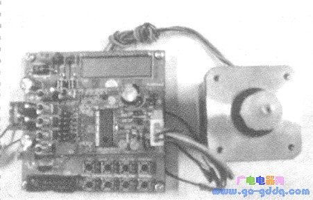
The working voltage of the whole system can be 24V or 12V. The main control MCU adopts MSP430FG413 of Tl MSP430 series. The main control board has 8 buttons. Through the button operation, the whole step mode, half step mode A and half step mode can be realized. B, 1/4 step, acceleration, deceleration, standby and other functions, and can display the current working status through the LCD interface.
This DEMO provides detailed technical information, BD6389 user manual, BD6389 control code, DEMO instructions, etc., greatly reducing the time for engineers to master BD6389 performance and two-phase motor control methods, shortening the development cycle.
4. in conclusion
In the field of motor control, it is especially important to choose a suitable stepper motor driver IC and fully understand the performance of the motor driver IC. Rohm's BD6389 and its family of chips are the most powerful two-phase motor driver ICs from ROHM, with a wide range of applications.
This website tries to open micro- and small-enterprise business advertising business; maintenance point recommended items. The fee is affordable and effective! Welcome to contact in QQ or email!
Why do you want to do online advertising contact?
- 0
- like
| Try to find the information you want to see. Inverter sensor patch three no weight loss camera LCD monitor does not boot digital camera XC9237 projector switching power supply laptop processor IPSUSB skills entrepreneurial black screen water heater can not boot circuit design silent transformer XC6102 without sound XC6112 display regulator no image microwave player successful silent GPS tea no picture XC6222 health XC6372 relay filter ML6209 switch washing machine digital camera description remote control without grating 555 protection circuit cancer self-closing Linux charger mobile phone shutdown noise inverter oscilloscope robot Windows antenna indicator light is not bright fiber life transformer stomach market alarm Hard disk watch embedded system woman maintenance process memory XC9236 converter router interview server kidney RFIDLED driver Konka CDMA instrument Panasonic CCD flashing engine multimeter Apple liver motor resistance keyboard integrated circuit current transformer triode governor power supply LED |
Portable Battery ,Portable Power Bank,Portable Battery Pack,Portable Power Pack
Zhejiang Casnovo Materials Co., Ltd. , https://www.casnovonewenergy.com