In the production of lithium batteries, assessing battery capacity and performance is one of the most important aspects. From low-capacity (10A) for mobile phones, camcorders, and hybrid vehicles, to medium capacity (10A-30A) for computers, electric motorcycles, and electric vehicles, to electric vehicles (30A-120A) High-capacity lithium-ion batteries, all without exception, require testing to be shipped from the factory.
According to Li Qiang, system application engineer of Analog Devices' Asia Pacific Precision Instrument Business Unit, the most common practice in the industry is to test linear test equipment for small-capacity batteries. Although it is inefficient and accurate, it is acceptable. However, if this test equipment is also used for high-capacity battery testing, it will consume a lot of power during the charging phase, resulting in inefficiency, and will bring quite serious thermal problems to the hardware design of the device.
To this end, ADI has designed the AD8450/1 precision analog front-end and controller and the ADP1972 buck/boost PWM controller for low-, medium-, and high-capacity three-capacity lithium-capacitor-capacitorization devices, eliminating the previous battery energy discharge. The linear architecture to the resistive load is instead efficient by providing current through the PWM controller and directing it back to the grid or charging other batteries.

The test data shows that in the charging mode, when the voltage is 3.5V, the efficiency value of 20A is 88%, and the efficiency value of 10A is 90%; and in the discharge mode, when the voltage is 3V, the efficiency value of 20A is 89%, the efficiency of 10A is 92%. In addition to efficiency, lithium battery companies are more concerned with cost and reliability. Li Qiang said that the lithium battery test solution on the market also has a discrete device combination scheme, which may use more than ten devices. The ADI solution uses only two chips, the AD8450/1 and ADP1972, which are highly integrated and have a greatly reduced design size. And by increasing the switching frequency to 300KHz, sharing high-cost DACs and ADCs with lower cost among multiple channels, and adding phase-shift synchronization between channels, input filtering can be reduced and the total system cost can be reduced. At the same time, ADI also provides users with design tools and full reference design to minimize development costs and design difficulties, and shorten the development cycle.
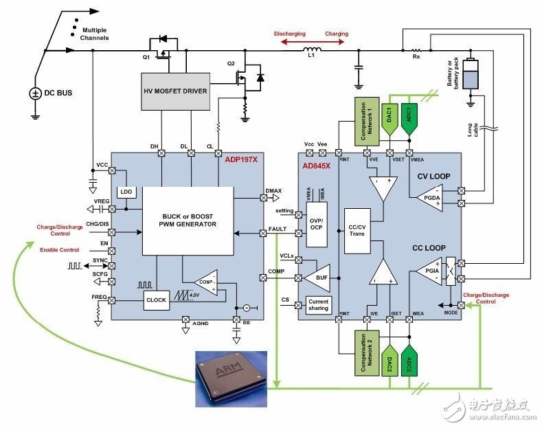
ADI Solution System Block Diagram
How do you share DACs and ADCs across multiple channels?
The figure above contains two functions: one is to charge the battery, and the other is to discharge the battery, which is determined by the mode signals of the AD8450/1 and ADP1972. There are two modes for each function: constant current (CC) mode and constant voltage (CV) mode. Two DAC channels control the CC and CV set points. The CC set point determines how much current is in the loop in CC mode for both charging and discharging functions. The CV set point determines the battery potential at which the loop enters the CV from the CC, as well as the two functions of charging and discharging.
The precision analog front end and controller AD8450/1 measures the battery voltage using the internal differential amplifier PGDA and measures the current on the battery using the internal instrumentation amplifier PGIA and an external shunt resistor (RS). It then compares the current and voltage to the DAC set point through an internal error amplifier and an external compensation network (used to determine whether the loop function is CC or CV). After this module, the output of the error amplifier enters the PWM controller ADP1972 to determine the duty cycle of the MOSFET power stage. Finally, the inductors and capacitors that make up the complete loop. The instructions in this section address both charging and discharging functions because the ADP1972 is a buck and boost PWM controller.
In this scenario, the ADC obtains a reading of the loop voltage and current, but it is not part of the control loop. The scan rate is independent of the performance of the control loop, so an ADC can measure the current and voltage of a large number of channels in a multi-channel system. The same is true for DACs, so multiple channels can be set up using low cost DACs. In addition, a single processor only needs to control CV and CC setpoints, operating modes, and management functions, so it can interface with many channels.
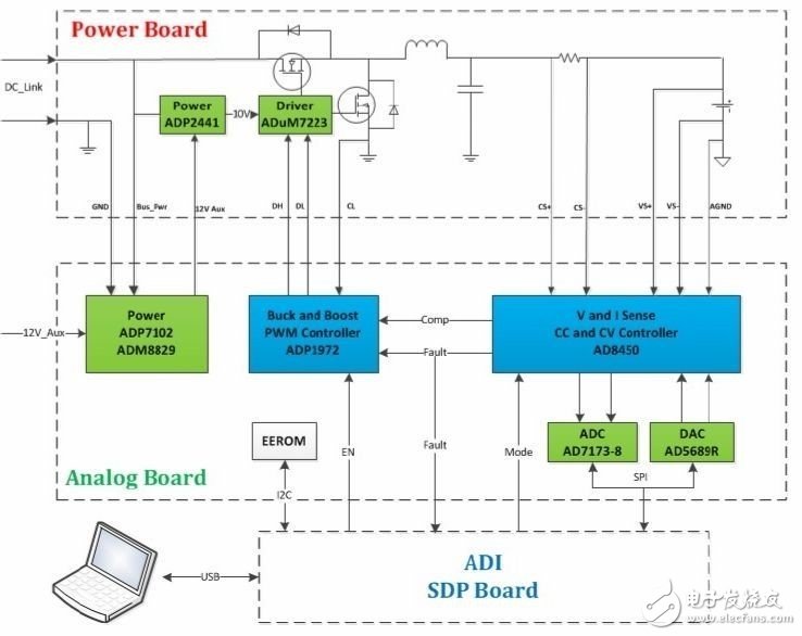
ADI AD8450/1 and ADP1972 demo block diagram
Maskking(Shenzhen) Technology CO., LTD , https://www.szelectroniccigarette.com