First of all, everyone needs to be clear about the difference between the sampling clock synchronization we talked about this time and the carrier synchronization we talked about last time. The receiver ADC samples the received continuous waveform, and the transmitter's DAC and receiver's ADC may not have exactly the same clock frequency and phase. The sampling bias in the time domain causes the subcarriers in the frequency domain to be no longer orthogonal, which is fatal for OFDM. The method of compensating for the sampling offset can be performed in the time domain (before IFFT) or in the frequency domain (after IFFT). We use pilot signals to compensate in the frequency domain.
First, the basic principle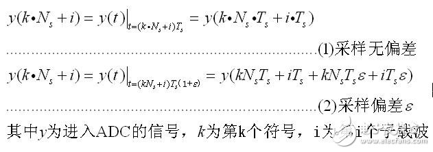
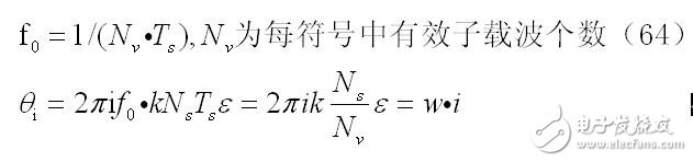
It can be seen that the sampling deviation is reflected in the last two items on the right side of (2). We ignore the fourth item, and the third item is the main error. This time domain deviation causes the frequency domain to rotate as follows:
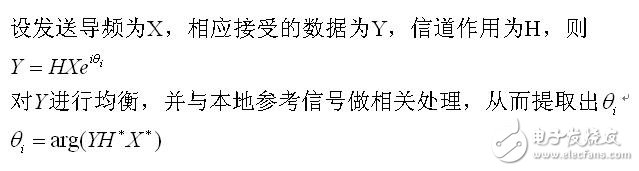
If we estimate the w using the pilot information (reference signal in LTE), then we can compensate for the accepted data.
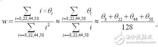
Since the IEEE 802.11a system specifies four pilot signals in one symbol, a linear equation system can be obtained. The approximate solution that is easy to implement in hardware is given in Reference [1] as follows:
In addition, when the sampling deviation is greater than T (subscript s), that is, the frequency domain phase rotation is greater than 2 pi, at this time, the sampling time has been advanced or delayed by one clock cycle, and retiming is required. So our system block diagram is:
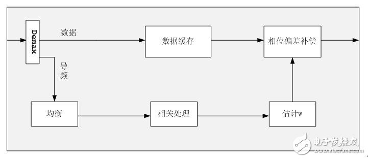
Second, each unit implementation method (1) pilot extraction:
In order to realize the pipeline operation, two 64-bit RAM are used to store the input data symbols in turn, and are extracted according to the fixed position where the pilot is located, and sent to the channel equalization module.
(2) Channel equalization:
By calling the complex multiplier, if channel estimation and equalization have been done before this design, then there is no need to do it again.
(3) Related processing:
Since the locally stored pilot signal (the original signal sent by the sender) is only positive or negative 1, the related operation either takes the data in the opposite direction or remains unchanged, which saves resources.
(4) estimate of w:
In two steps, first estimate the phase angle theta, using the Cordic module to achieve, pay attention to the overflow problem, refer to the previous blog on the carrier synchronization processing method. The second part is to add the estimated four angles and shift the right by 7 digits.
(5) Phase deviation compensation:
As the data is entered, accumulate w (note the overflow problem), calculate its sine cosine value, and call the complex multiplier to compensate. Similar to carrier frequency compensation.
Relative to SC To SC UPC Duplex,Optical fiber jumpers (also known as optical fiber connectors), that is, optical fiber connectors that are connected to optical modules, are also available in many types, and they cannot be used mutually. The SFP module is connected to the LC fiber optic connector, and the GBIC is connected to the SC fiber optic connector. The following is a detailed description of several commonly used optical fiber connectors in network engineering:
â‘ FC-type fiber jumper: The external strengthening method is a metal sleeve, and the fastening method is a turnbuckle. Generally used on the ODF side (most used on the distribution frame)
â‘¡SC type optical fiber jumper: the connector that connects to the GBIC optical module, its shell is rectangular, and the fastening method is a plug-in latch type, without rotation. (Most used on router switches)
â‘¢ST type optical fiber jumper: commonly used in optical fiber distribution frame, the shell is round, and the fastening method is turnbuckle. (For 10Base-F connection, the connector is usually ST type. Commonly used in optical fiber distribution frame)
â‘£LC-type optical fiber jumper: the connector for connecting the SFP module, which is made by the easy-to-operate modular jack (RJ) latch mechanism. (Router commonly used)
Sc To Sc Upc Duplex,Sc To Sc Upc Simplex,Sc Upc To Sc Apc Simplex,Sc To Sc Apc Duplex
Nanjing Jisu Shitong Technology Co., Ltd , https://www.netairs.com